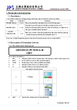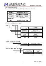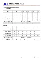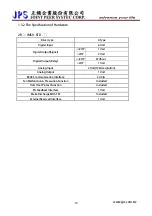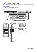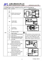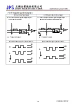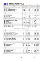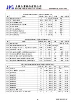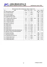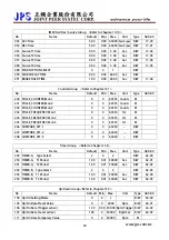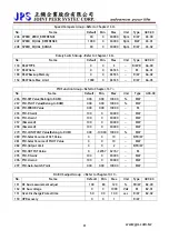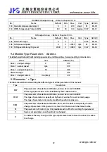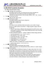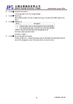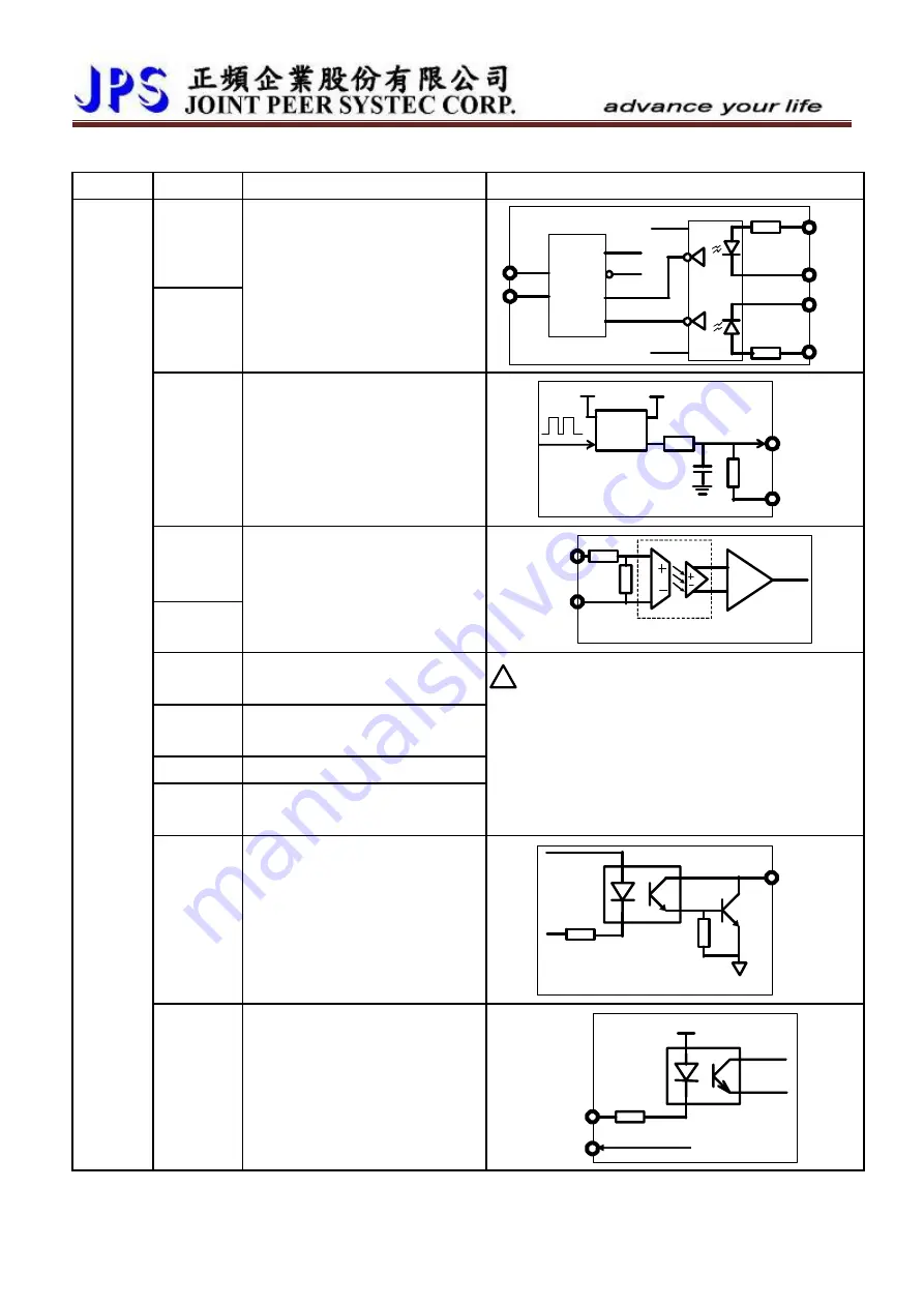
7.2 CON6 Comm., DI/O, AI, AM, PG_in, PG_out, XY_in Description
Terminal
Name
Function
Hardware construction
PLC
485-A
PLC
485-B
RS485 communication port
(photo coupler isolated)
TE
VCC
TX
VCC
R
GND
RE
DE
D
B
A
VCC
485-
485-B
RX
GND
AM1
Analog output
(refer to ACOM)
ACOM
R
AM1
PWM Waveform from CPU
Photo
coupler
C
AI1
AI2
Analog Input
(refer to ACOM)
ACOM
To CPU
AI(x)
12Bit Resolution Analog Input
OP
T5V
5V reference voltage
(refer to ACOM)
ACOM
The reference ground of Analog
signal system.
24V
24V output power (refer to G24).
G24
The reference ground of digital
I/O system.
!
NOTE
1.
ACOM and G24 are not the same electric level.
2.
5V is used to be a voltage reference for analog
signal; 24V is used for digital input / output
signal connection; do not use both these two
voltage as power supplier to external circuits.
DO1 ~DO3
Digital output terminals.
(reference ground is G24)
Only be used under 24V voltage
level to keep system stable.
Programmable by setting
parameter value.
Signal
from CPU
G24
Open Collector
DO-(x)
Digital Output
CON6
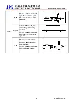
DI1 ~ DI6
Digital input terminals.
(reference ground is G24)
Only be used under 24V voltage
level to keep system stable.
Programmable by setting
parameter value.
4.7K
G24
+24V
GND
To CPU
G24
DI-(x)
Digital Input
www.jps.com.tw
21
Содержание IRIS-IMSV
Страница 1: ...IRIS IMSV DRIVER USER MANUAL Version V5 03 ...
Страница 95: ...16 CE Certificate 16 1 EMC Certificate www jps com tw 94 ...
Страница 96: ...16 2 LVD Certificate www jps com tw 95 ...

