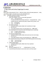
8.Quick Start
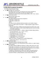
8.1Run Command Set from Digital Input Terminals
!
NOTE!
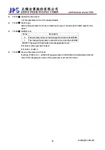
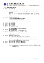
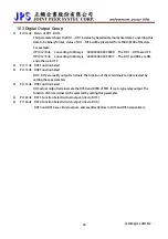
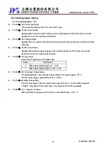
Please make sure the specification of motor’s feed back encoder, and check the related parameters’ setting
value. Refer to Chapter 0 10.6 Encoder Sensor Group for detailed description.
Step I
Setting Basic Parameters and Auto Tuning (Close Loop)
A.
Setting the Parameter of Motor
Refer to the nameplate on motor to set the following parameters:
1.
Pr.210
Full Load Current (%)
This parameter defines the percentage of the motor’s rating and the driver’s rating.
Full Load Current (%) = (Rated Current of Motor / Rated Current of Driver) x 100%
2.
Pr.116
Motor Pole No.
3.
Pr.128
Max. RPM Limit
B.
Execute R&L Auto Tuning
1.
Setting Pr.003 (Motor Operation Mode) to be 7 (select R&L Auto Tuning).
2.
Reset the driver.
3.
Connect FWD and G24 terminals, and wait till display shows
【END or do】
After completing R&L Auto Tuning, driver will set following parameters automatically:
1.
Pr.216
the phase resistance of motor.
2.
Pr.217
the phase inductance of motor.
C.
Execute Current Gain Auto Tuning
1.
Setting Pr.003 (Motor Operation Mode) to be 6 (select Current Gain Auto Tuning).
2.
Reset the driver.
3.
Connect FWD and G24 terminals, and wait till display shows
【END or do】
After completing Current Gain Auto Tuning, driver will set following parameters automatically.
1.
Pr.004
Current Loop P-gain
2.
Pr.005
Current Loop I-gain
D.
Set Motor Operation Mode
1.
Setting Pr.003 (Motor Operation Mode) to be 2 (Close Loop Mode.)
2.
Reset the driver.
Step II
Start to Run
1.
Setting Pr.120 (Speed Set 0) = 100.
Æ
Setting Speed Set 0 = 100 rpm.
2.
Connect FWD and G24 terminals, the motor will start and run at 100 rpm speed
www.jps.com.tw
24
Содержание IRIS-IMSV
Страница 1: ...IRIS IMSV DRIVER USER MANUAL Version V5 03 ...
Страница 95: ...16 CE Certificate 16 1 EMC Certificate www jps com tw 94 ...
Страница 96: ...16 2 LVD Certificate www jps com tw 95 ...

