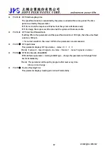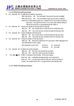
background image


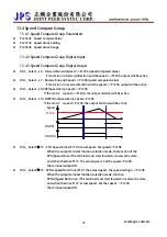
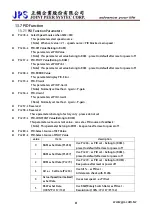
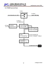
13.7.2 PID Function Digital-Input 

z


DIx_Select 

Æ

  70,PID -->    ENABLE PID Block 


  When select this function,enable PID block。   


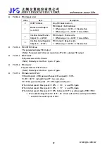
13.7.3 PID Function Digital-Output 


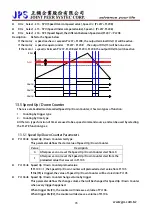
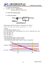
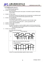
13.7.4 PID Function Block   


PID Set 

PID Pilot

PID Error

PID Process

  P Gain 

  I Gain 

PID Output 

PID Enable DIx(70)


PID block compare with PID-Set and PID-Pilot,and produce the result:PID-Error 

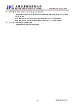
Formule:

----------------(1-1) 

dt


Error

Igain

Pgain

Error

Output

PID

+

×

=

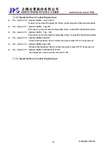
【Example】: 

Pr.128:Motor Maximun speed limit  = 1000 

Pr.297:PID-switch point = 80.20   

Î

XX =(800/1000)×100%  = 80%;YY =(200/1000)×100%  = 20% 

Pr.255:PID P- gain1 = 500 

Pr.256:PID I - gain1 = 50 

Pr.295:PID P-gain2  = 100 

Pr.296:PID I - gain2 = 10 

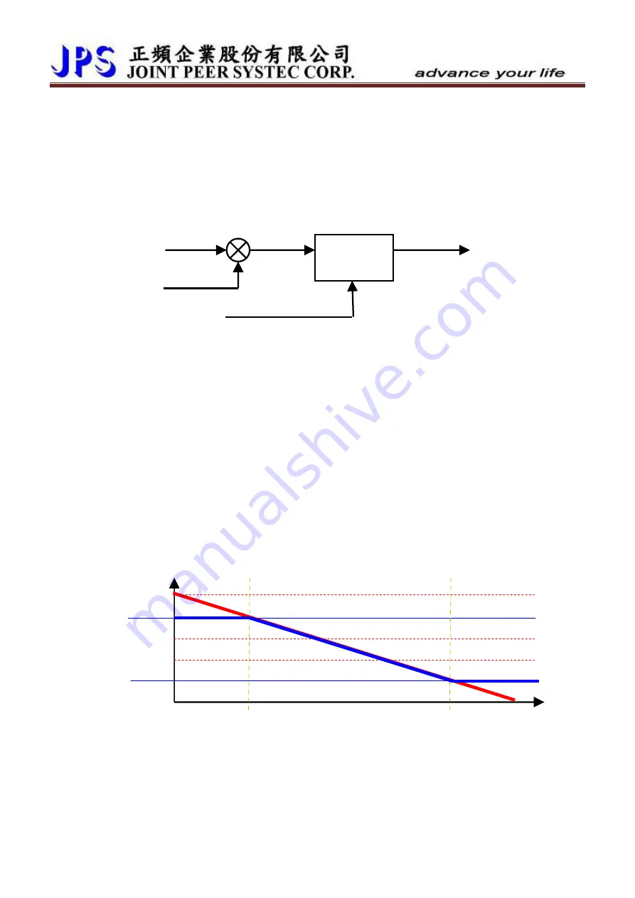
※ When actually speed > 800rpm,main gain = PID- Gain1 

※ When actually speed < 200rpm,main gain = PID-Gain2 

※  When actually speed between 200rpm ~ 800rpm,main gain = linear adjustment。 


Rpm 

1000 


www.jps.com.tw                 

83

PID High Gain 

20% 

800 

600 

400 

200 

PID Low Gain 

80% 


Содержание IRIS-IMSV

Страница 1: ...IRIS IMSV DRIVER USER MANUAL Version V5 03 ...

Страница 2: ...er depends on the correct installation commissioning operation and maintenance of the device z This device operates at high voltages CAUTION z The DC link capacitors remain charged to dangerous voltages even the power is removed For this reason it is not permissible to open the inverter cover until five 5 minutes after the power has been turned off z When handling the open inverter it should be no...

Страница 3: ...ely call attention to information that is especially significant in understanding and operating the inverter DANGER and WARNING z Make sure that the location selected for installation is safe protected from moisture and splash and drip proof z Children and the general public must be prevented from accessing or approaching the equipment z The equipment may only be used for the purpose specified by ...

Страница 4: ...5 5The Proper Screw Drive for Power Terminals 16 6 Basic Wiring Diagram for IRIS Series Drive 17 7 I O Interface 18 7 1The Map of I O Terminal Position 18 7 1 1 0 5 2HP Input Output terminal on front side 18 7 1 2 0 5 2HP Input Output terminal on back side 19 7 1 3 3 30HP Input Output terminal on front side 20 7 1 4 Definition of control signals 20 7 2 CON6 Comm DI O AI AM PG_in PG_out XY_in Descr...

Страница 5: ...t Function 63 13 Flip Flop Function Description 65 13 1 Pulse Couter Group 65 13 1 1 Pulse Counter Parameters 65 13 1 2 Pulse Counter Digital Input 65 13 1 3 Pulse Counter Digital Output 65 13 2 FlipFlop Group 66 13 2 1 FlipFlop Group Parameters 66 13 2 2 FlipFlop Group Digital Input 66 13 2 3 FlipFlop Group Digital Output 66 13 2 4 General Flip Flop 67 13 2 5 D Type Flip Flop 68 13 2 6 T Type Fli...

Страница 6: ...ital Output 83 13 7 4 PID Function Block 83 14 PCMD Mode 84 14 1 PCMD Rule 84 14 2 PCMD Connection 84 14 3 PCMD Function Block 85 14 4 PCMD Function Group 86 14 4 1 PCMD Group Parameters 86 14 4 2 PCMD Group Digital Input 88 14 4 3 PCMD Group Digital Output 88 14 5 PCMD Function Basic Example 89 14 5 1 PCMD Parameter Setting 89 14 5 2 PCMD Start 89 15 Alarm Message and Maintenance 90 15 1 Display ...

Страница 7: ...onitor Mode MON MODE 100 17 2 3 Parameter Editing Mode PAR MODE 101 17 2 4 ALARM MODE ALM MODE 101 17 2 5 RD WT Single Word Double Word Parameters 102 17 2 6 Single Word Double Word Negative Numbers 103 17 2 7 Alarm Mode of R Panel ALM Code Description 104 17 2 8 Definition of Cables 104 ...

Страница 8: ...d been tested before packing Attachedonlywhendriverratedcurrenthigherthan11A If any miss or defect happened please contact with the agency to get resolve of the problem 1 2 Description of Nameplate Content 1 2 1 The Label on the Packing Case 2R5 IMSV PCMD A R 220V The contents of indication 1 2R5 Æ Indicates that this driver should access 220 Volt power and the rated output is 5A 2 IMSV Æ Suit for...

Страница 9: ...ating label are showed below 2 220VAC Input voltage 4 380VAC Model series R IRIS Series Output current According to Driver Current Suit motor IMSV Induction Motor Type Firmware Standard Function Factory Only Panel R Panel MODEL 2 R IMSV STD A R Power Type A C 1 or 3 Phase 220Volt Power Frequency 50Hz 60Hz INPUT AC3Ø220 50 60HZ Phase Current 3Phase 5A Capacitance KVA 2KVA Output Frequency Range 0 4...

Страница 10: ...5 1 3 1 8 2 5 4 0 6 5 9 5 13 19 25 34 Rated Power KW 0 4 0 75 1 1 5 2 2 3 7 5 5 7 5 11 15 22 5 Max Output Voltage V Match 3 phase Input Voltage Dimension P1 P2 P3 P4 380V Series 4R 5P5 8P5 12 17 23 31 45 Output Current A 5 5 8 5 12 17 23 31 45 Horse Power HP 3 5 7 5 10 15 20 30 Rated Capacity KVA 4 0 6 5 9 5 13 19 25 34 Rated Power KW 2 2 3 7 5 5 7 5 11 15 22 5 Max Output Voltage V Match 3 phase I...

Страница 11: ...Signal 2HP 2 Unit 2HP Without Digital Output Relay 2HP 1 Unit Analog Input 2 Unit 12bit resolution Analog Output 1 Unit RS485 Communication Interface 2 Units Fan Malfunction Precaution Function Included Over Heat Protect Function Included PG Feedback Interface 1Unit Brake Discharge MOS FET Included External Received Interface 1 Unit ...

Страница 12: ...ons as well as the relevant regulations regarding the correct use of tools and personal protective gear Make sure that the unobstructed clearance for each of the cooling inlets and outlets above and below the inverter is at least 100mm Make sure that a space of 40mm is kept free at the sides of the inverter to permit the cooling air to escape from the side slits 10cm 4cm 10cm 4cm Cooling Air 保持 Co...

Страница 13: ...4 Outline Dimension P1 0 5HP 2HP Unit mm P2 3HP 5HP Unit mm P3 7 5 HP 10HP Unit mm P4 15HP 30HP Unit mm www jps com tw 12 ...

Страница 14: ...z There are static sensitive components inside the Printed Circuit Board Avoid touching the boards or components with your hands or metal objects z Make sure to connect the power terminals tight and correctly z Make sure that the power source supplies the correct voltage and is designed for the necessary current z The terminal has icon should be connected to Earth properly 5 1 2The Output Terminal...

Страница 15: ...choosing resistor for braking discharge The wattage of resistor can be increased for heavier re generating energy or higher discharge duty Model Resistance ohm Wattage W 2R2 400 40 2R3P5 300 60 2R5 200 80 2R7 100 150 2R11 60 250 2R17 40 300 2R24 30 500 2R33 20 600 2R46 15 1000 2R61 10 1500 2R90 10 2000 4R5P5 250 250 4R8P5 150 300 4R12 100 500 4R17 75 750 4R23 50 1000 4R31 40 1500 4R45 40 2000 The ...

Страница 16: ...rb instantaneous current and to improve power efficient ratio Refer to the list below to choose proper reactance Voltage V Model Current A Inductance 2R2 6 1 8mH 2R3P5 6 1 8mH 2R5 6 1 8mH 2R7 10 1 1mH 2R11 11 0 71mH 2R17 17 0 53mH 2R24 24 0 35mH 2R33 33 0 26mH 2R46 46 0 18mH 2R61 61 0 13mH 220 2R90 120 0 09mH 4R5P5 7 5 3 6mH 4R8P5 10 2 2mH 4R12 15 1 42mH 4R17 20 1 0mH 4R23 30 0 7mH 4R31 40 0 53mH ...

Страница 17: ...ssary to choose proper tool for wiring connection to avoid screw stripped or burst Please refer to the list below to choose a proper screw drive for driving power terminals A B mm C mm D mm P mm L mm 0 6 3 3 3 3 B C mm D mm P mm L mm 0 3 3 www jps com tw 16 ...

Страница 18: ...BT 0V 10V RANGE 10V 10V RANGE G24 REV FWD DI4 DI3 DI2 DI1 PHOTO ISOLATED DIGITAL INPUT PORT MOTOR R S T E ACOM V5T ACOM AM1 RY3A RY3B MAX RATING 200V 3A OPEN COLLECTER 24V DO1 DO2 U V W POTENTIAL METER AI1 BRAKE 24V LCD 485 G24 DO3 24V 485 B 485 A TO PLC HMI www jps com tw 17 ...

Страница 19: ... 5V AM1 485B 485A ACOM 24V G24 XY_IN PIN Signal 1 X 2 X 3 Y 4 Y 5 6 7 5V 8 ACOM 9 FG SHIELD DB1 F XY_IN DB2 M PG_IN PG_IN 1 A 2 A 3 B 4 B 5 C 6 C 7 8 9 10 11 12 13 V5 14 15 PGND FG SHIELD TM1 Terminal Spec IEC 130V 8A Digital Input DI1 DI6 Digital Ouput DO1 DO3 Voltage Ground G24 TM2 Terminal Spec IEC 130V 8A Voltage Output 4V Analog Output AM1 Analog Input AI1 AI2 Voltage Output T5V ACOM RS485 Co...

Страница 20: ... OUT PG_OUT CON9 9PinD sub Male Signal Pin1 Pin 1 OA Pin2 Pin 2 OA Pin3 Pin 3 OB Pin4 Pin 4 OB Pin5 Pin 5 OC Pin6 Pin 6 OC Pin 7 Pin7 Pin 8 VSS D Pin 9 Pin8 FG SHIELD DB3 M PG_OUT PG_OUT use cable with DB9M SC8P 0 5M DB9M SC8P 0 5M Optional www jps com tw 19 ...

Страница 21: ...tor defined CON8 D sub9 F definition Pin1 Pin1 X Pin2 Pin2 X Pin3 Pin3 Y Pin4 Pin4 Y Pin5 N C Pin6 N C Pin5 Pin7 5V Pin6 Pin8 0V Pin9 N C Pin7 shell shield PG OUT caption Wire name D09M SC08P 0 5M Connector defined CON6 D sub9 M definition Pin1 Pin1 Aout Pin2 Pin2 Aout Pin3 Pin3 Bout Pin4 Pin4 Bout Pin5 Pin5 Cout Pin6 Pin6 Cout Pin7 N C Pin7 Pin8 0V Pin9 N C Pin8 shell shield Connector defined PG1...

Страница 22: ... The reference ground of digital I O system NOTE 1 ACOM and G24 are not the same electric level 2 5V is used to be a voltage reference for analog signal 24V is used for digital input output signal connection do not use both these two voltage as power supplier to external circuits DO1 DO3 Digital output terminals reference ground is G24 Only be used under 24V voltage level to keep system stable Pro...

Страница 23: ...OUT Inside the IRIS drive PG_OUT and PG_IN signal is derectly connected The input hardware structure of signal OB OC is same as signal OA OA OA A A CON6 XY_IN The XY pulse input hardware structure is design as 5V Line Drive type input The input hardware structure of signal Y is same as signal X 220 1 4W X X X Vcc www jps com tw 22 ...

Страница 24: ...st connect to terminal 220 1 4W X X X Vcc ps Y signal X signal z If use 24V Open Collector signal as digital input Need to connect limit resistance 2K 1W 220 1 4W 24V X X Vcc X 2K 1W ps Y signal X signal Use 5V Line Driver signal please refer to Open Collector Signal please refer to X X X 5V 0V 5V 0V 5V 0V X X 5V 0V 24V 0V www jps com tw 23 ...

Страница 25: ...ct R L Auto Tuning 2 Reset the driver 3 Connect FWD and G24 terminals and wait till display shows END or do After completing R L Auto Tuning driver will set following parameters automatically 1 Pr 216 the phase resistance of motor 2 Pr 217 the phase inductance of motor C Execute Current Gain Auto Tuning 1 Setting Pr 003 Motor Operation Mode to be 6 select Current Gain Auto Tuning 2 Reset the drive...

Страница 26: ...listed below When driver is in Forward Run condition and the motor rotating in CCW direction face to the motor axis 1 Setting Pr 065 FWD terminal function select to be 0 Î Disable FWD terminal functions 2 Turn off AC input power 3 Connect the U V W wires to the terminals U V W of driver Î Change the output power lines 4 Turn on the AC input power 5 Setting Pr 188 Encoder sensor direction to be 1 Î...

Страница 27: ...1 17 061 DI1 function select 0 0 255 R W 01 01 062 DI2 function select 0 0 255 R W 01 02 063 DI3 function select 0 0 255 R W 01 03 064 DI4 function select 0 0 255 R W 01 04 065 FWD DI5 function select 73 0 255 R W 01 05 066 REV DI6 function select 74 0 255 R W 01 06 068 The Run Stop keys function select 0 0 255 R W 01 08 475 DI15 function select a virtual input links to DO15 0 0 255 R W 01 15 476 ...

Страница 28: ...0 100 00 R W Analog Output Group Refer to Chapter 10 5 No Name Default Min Max Unit Type GXX XX 370 AMOUT Select Data 0 0 15 R W R 05 00 371 AMOUT Full Scale Data Range 0 0 65535 FR W 05 01 372 AMOUT Test Data 0 100 Full scale 0 0 0 0 100 0 RAM 05 02 373 AMOUT 100 Full Scale adjustment 0 0 0 0 100 0 FR W 05 03 374 AMOUT 75 adjustment 0 0 0 0 100 0 FR W 05 04 375 AMOUT 50 scale adjustment 0 0 0 0 1...

Страница 29: ... R W 210 Full Load Current of AMP Rating Current 50 0 200 FR W 10 00 211 Filed Current of Full Load Current 30 0 200 FR W 10 01 215 Electronic Over Load Thermal Relay Time 3 0 120 sec R W 10 04 216 RESISTANCE between V W U phase open 1 000 0 00 60 00 Ohm FR W 10 05 217 INDUCTANCE between V W U phase open 1 00 0 00 60 00 mH FR W 10 06 IMSV Multi Speed Setting Group Refer to Chapter 10 9 No Name Def...

Страница 30: ...0 0 1000 R W 15 07 033 1 st Speed Loop Filter 0 0 7 R W 15 08 086 Torque control mode 0 0 3 R W 15 13 087 Torque Limit I 100 0 0 0 300 0 R W 15 14 088 Torque Limit II 100 0 0 0 300 0 R W 15 15 089 Torque Limit III 100 0 0 0 300 0 R W 15 16 090 Torque Limit IV 100 0 0 0 300 0 R W 15 17 095 TorqueCompareLevel ofMotorRatedTorque 100 0 300 R W 15 20 096 Random Torque Command Setting RAM 0 0 0 0 300 0 ...

Страница 31: ...ts M 243 PULSE_FREQUENCY Mon1 0 0 65535 Hz M 244 PULSE_FREQUENCY Mon2 0 0 65535 Hz M 245 PULSE_FREQUENCY Mon3 0 0 65535 Hz M 246 COMPARE_SET 1 0 0 65000 R W 247 COMPARE_SET 2 0 0 65000 R W 248 COMPARE_SET 3 0 0 65000 R W Timer Group Refer to Chapter 13 3 No Name Default Min Max Unit Type GXX XX 249 TIMER A Type Select 2 0 2 R W 62 00 250 TIMER A T1 Period 1 00 0 01 300 00 Sec R W 62 01 251 TIMER A...

Страница 32: ... W 237 PID PILOT Value Belong to RAM 0 00 0 00 100 00 R W 238 PID ERROR Value 0 00 0 00 100 00 M 255 PID P Gain1 100 0 30000 R W 256 PID I Gain1 100 0 30000 R W 257 Reserved 100 0 30000 R W 258 Reserved 100 0 30000 R W 279 PID CONSTANT Value Belong to ROM 0 00 100 00 100 00 R W 280 PID Select Source of SET Value 0 0 10 R FR W 281 PID Select Source of PILOT Value 0 0 10 R W 282 PID Output Limit 0 0...

Страница 33: ...tput current rms Amp 213 9 3Parameter s Type The table showed below describing the different type of all the parameter of this manual Type Description R W The parameter is Readable and Writable and can be stored in EAROM All this type parameters can be initialized by the Pr 369 function FR W The parameter is Readable and Writable and can be stored in EAROM This type of parameter is specially set b...

Страница 34: ...ow this parameter s setting to calculate the followed voltage check level Over Potential trip level 1 414 Pr 130 130 OP recover level 1 414 Pr 130 120 Under Potential trip level 1 414 Pr 130 70 UP recover level 1 414 Pr 130 80 CONTACTOR ON level 1 414 Pr 130 69 CONTACTOR OFF 1 414 Pr 130 65 NOTE The Contactor is inside the driver to short the charging resistor Brake Discharge start level 1 414 Pr ...

Страница 35: ...scription 0 The parameter value can be changed and stored into EAROM 1 The change of parameter value will not be stored into EAROM NOTE The value of Pr 368 will not be changed after reset If Pr 368 0 after reset the Pr 368 0 If Pr 368 1 Pr 368 1 z Pr 369 Î Recover Parameters to Default If setting Pr 369 to be 1 all the R W type parameters in EAROM will be initialized to default value After changin...

Страница 36: ...DI5 Function Select FWD terminal has been set to be 73 Î Forward Run z Pr 066 Î REV DI6 Function Select REV terminal has been set to be 74 Î Reverse Run z Pr 067 Î FAN running status Factory set cannot be changed This parameter is fixed set by factory and cannot be changed The FAN running status will showed on the bit7 of Pr 011 z Pr 068 Î The Run Stop keys function select Only in Monitor mode or ...

Страница 37: ...1 and DO3 are ON and others are OFF z Pr 111 Î DO1 Function Select z Pr 112 Î DO2 Function Select DO1 DO2 are reality output terminals The function of these terminals can be selected by setting these parameters z Pr 113 Î DO3 Function Select DO3 actual output terminals are the RY3A and RY3B of TM1 It is a A type relay output The function of this terminal can be selected by setting this parameter z...

Страница 38: ...oltage to AI1 read the data from Pr 229 and set into this parameter as the AI1 input minimum limit z Pr 233 Î AI1 Input Type Select the AI1 input type of voltage range Value Description 0 The input voltage range is 0 10V 1 The input voltage range is 10V 10V z Pr 234 Î AI1 Display of Input Value The displayed data AI1 actually input voltage AI1 input range x 100 The AI1 input range is adjusted by P...

Страница 39: ...input voltage to AI2 read the data from Pr 477 and set into this parameter as the AI2 input minimum limit z Pr 484 Î AI2 Input Type Select the AI2 input type of voltage range Value Description 0 The input voltage range is 0 10V 1 The input voltage range is 10V 10V z Pr 485 Î AI 2 Command Value The displayed data AI2 actually input voltage AI2 input range x 100 The AI2 input range is adjusted by Pr...

Страница 40: ...4012 Set Pr 230 4012 Input 0V to AI1 and read Pr 229 2014 Set Pr 231 2014 Input 10V and read Pr 229 18 Set Pr 232 18 By the equation 3000 4012 2014 1 5 to know that one A D count is about 1 5rpm By the equation 20x1 5 30 to know the range of Blind Zone is 30rpm If the input voltage of AI1 is in the range of 2014 20 the motor will not run If the input voltage of AI1 exceeds f the range of 2014 20 t...

Страница 41: ...mand 9 Reset the driver Î Change Pr 278 must reset driver VR TM2 485B 485A 24V ACOM AM1 5V AI1 ACOM 24V Example 3 Using external 10V 10V signal as speed command 1 Wiring the input signal lines to control terminals as the figure showed below 2 Setting Pr 233 1 Î Select AI1 input range 10V 10V 3 Input maximum voltage to AI1 read Pr 229 4 Write Pr 229 value into Pr 230 Î Setting AI1 maximum value 5 I...

Страница 42: ...uracy is 0 01Hz Select 2 Æ The output of AM1 presents the driver s output current The accuracy is 0 1A Select 3 Æ The output of AM1 presents the driver s output voltage The accuracy is 1V Select 4 Æ The output of AM1 presents the motor s actual speed The accuracy is 1rpm Select 5 9 Æ All these are reserved Should not select these function numbers for operation safety Select 10 Æ AM1 send out 100 v...

Страница 43: ... scale 20 0A Î the full scale should set to be 200 Voltage Meter full scale 500V Î the full scale should set to be 500 Speed Meter full scale 1800rpm Î the full scale should set to be 1800 z Pr 372 Î AM1 Output Volume Setting IF Pr 370 select function 15 the output of AM1 is set by this parameter The range of this parameter is 0 0 100 0 z Pr 373 Î AM1 100 Full Scale Adjustment Be used for AM1 100 ...

Страница 44: ...s not in proper position adjust by the VR knob of the meter 5 Pr 370 11 Î Set AM1 function to send 75 scale output 6 Execute RESET Î Reset the driver 7 Pr 374 check the meter to set Î Adjust the Pr 374 to let the meter point to 1800x75 1350 8 Pr 370 12 Î Set AM1 function to send 50 scale output 9 Execute RESET Î Reset the driver 10 Pr 375 check the meter to set Î Adjust the Pr 375 to let the meter...

Страница 45: ... pulse The range of the counter is 0 65535 z Pr 192 Î Encoder Sensor Input Buffer Size If using 256 pps sensor Pr 192 should set 6 If Using 1024 pps sensor Pr 192 should set 2 z Pr 193 Î ENCODER CHECK TIME This parameter is used to set the check time for driver to check the PG signal at every time the speed command be send to check if the encoder sensor is in good condition Every time the driver s...

Страница 46: ... driver s rating Motor Full Load Current ratio motor s full load current driver s rating current x100 z Pr 211 Î Filed Current of Full Load Current Set the ratio of the motor s exciting current to the motor s full load current MotorExcitingCurrentRatio motor sexcitingcurrent motor sfullloadcurrent x100 z Pr 215 Î Electronic Over Load Thermal Relay Time This Driver has built an electronic thermo fu...

Страница 47: ...op P gain Set the current loop P gain of the driver z Pr 005 Î Current Loop I gain Set the current loop I gain of the driver NOTE This parameter is auto set by executing Auto Current Gain Tuning Pr 004 should keep larger then Pr 005 z Pr 008 Î Current Loop Filter Level Define the current loop filter level z Pr 018 Î Speed Loop P I Gain Select Value Description 1 Only use the 1 st Gain 2 According ...

Страница 48: ...rant I 4 Direct Torque Control by RAM Pr 096 with Speed Limit 8 Torque Limit By Rotary Switch TL I Pr 137 Pr 152 9 Torque Limit By AI 2 TL I If Pr 086 select 0 The driver uses only Torque Limit quadrant I setting as torque limit Torque rpm Q Ⅰ Q Ⅱ Q Ⅲ Q Ⅳ Forward Forward rpm Torque Reverse Reverse Motor Generator Generator Motor Pr 128 Pr 128 Pr 087 Pr 087 If Pr 086 select 1 When the motor runs in...

Страница 49: ...verse Motor Generator Generator Motor Pr 128 Pr 128 Varied by AI1 Varied by AI1 If Pr 086 select 3 The torque is set by AI1 x Pr 087 Torque Limit quadrant I Torque rpm Q Ⅰ Q Ⅱ Q Ⅲ Q Ⅳ Forward Forward rpm Torque Reverse Reverse Motor Generator Generator Motor Pr 128 Pr 128 Pr 087 Pr 087 Varied by AI1 Varied by AI1 If Pr 086 select 9 Torque limit source AI2 similar Pr 086 1 www jps com tw 48 ...

Страница 50: ...n reverse direction and there is negative torque comes from load z Pr 090 Î Torque Limit IV Set the torque limit value when motor is running in quadrant IV In this guardant the motor is running in forward direction and there is negative torque comes from load Torque rpm Q Ⅰ Q Ⅱ Q Ⅲ Q Ⅳ Forward Forward rpm Torque Reverse Reverse Motor Generator Generator Motor z Pr 095 Î Torque Compare Level of Mot...

Страница 51: ... by linear manner when speed is in the range of 1000 1100rpm rpm RPM b Pr 128 x Pr 108 T Tcmd RPM a Pr 128 RPM a RPM b z Pr 110 Î Direction Limit Value Description 0 Permit forward and reverse direction run command 1 Only forward direction run command is permitted The reverse direction run command will stop the motor 2 Only reverse direction run command is permitted The forward direction run comma...

Страница 52: ...should keep larger then Pr 162 Example If set z Pr 029 300rpm z Pr 160 1500rpm rpm 1500 Gain 300 Max rpm 1 st Gain 2 nd Gain 1 When speed start from 0rpm to 300rpm under the 1 st gain switch point the driver uses the 1 st PI tuning parameters for close loop control 2 When speed is in the range of 300 1500rpm the driver will change the PI tuning parameters value from 1 st to 2 nd by linear manner 3...

Страница 53: ...s different speed and can be selected by digital input terminals NOTE If want to select Pr 120 Pr 127 speed the parameter Pr 278 must set 0 z Pr 128 Î Maximum RPM Limit Refer to the data from motor s manufacturer to get correct setting value z Pr 278 Î Select Speed Source when SWx 000 Value Description 0 The speed command select from Pr 120 Pr 127 setting 1 The speed command set from AI1 input 2 T...

Страница 54: ...mp time calculated from 1000 to 0rpm Unit precision is 0 01sec Pr 053 Acc Time 1000rpm 1500rpm 4 sec 5 sec rpm time 500rpm Pr 054 Dec Time 1000rpm According to the front figure Acc Time Pr 053 8 00sec Dec Time Pr 054 10 00sec The slope of rising ramp is 1000rpm 8sec the slope of falling ramp is 1000rpm 10sec Therefore from 0 to 1000rpm need 8 4 12sec from 1500 to 0rpm need 10 5 15sec www jps com t...

Страница 55: ... and deceleration time Speed Acc T1 T2 T3 T4 Example Explain how the S curve affects the Acc and Dec timing Ta Speed T 1000RPM If setting Pr 053 Acc Time 1 00 Sec Krpm and Pr 055 S curve T1 Time 1 00sec Pr 056 S curve T2 Time 1 00sec Ta totally acc time 0 5 x S curve T1 Time Acc Time 0 5 x S curveT2 Time 2sec z Pr 289 Î START OPTION SELECT Value Description 0 Select start speed from zero speed 1 S...

Страница 56: ...ke period Refer to the figure below When driver decelerate to 0 speed it will send a brake voltage to motor and hold for a period of time to make sure the motor actually stopped This time is called Brake Hold Time Brake Pr 054 Pr 291 Speed Output Voltage Run www jps com tw 55 ...

Страница 57: ... z Pr 132 Î DC Bus Voltage This parameter will display the measured DC bus voltage The relation of input AC power and DC bus voltage is Vdc 1 414 Vac input power z Pr 151 Î Over Discharge Protect Time This parameter can set the Over Discharge Protect Time to protect the discharge resistor If the discharge time exceeds this setting the driver will tip and show the Od alarm message NOTE When Pr 132 ...

Страница 58: ...will output warning signal by using digital output function 11 If Pr 148 Pr 149 x 0 5 the driver will trip and show CF alarm message NOTE If set Pr 149 to be 0 the protect function will be disabled WARNING It is important to keep the cooling fan in ordinary condition because there is lot of heat be generated while driving the motor If there happened the CF warning must check or replace the cooling...

Страница 59: ... Zero 29 Pulse Counter 3 CLEAR to Zero 13 1 30 FAN Detector Input 31 Pulse Counter 1 INPUT 32 Pulse Counter 2 INPUT 33 Pulse Counter 3 INPUT 13 1 60 TIMER A TRIG START input 13 3 61 TIMER B TRIG START input 70 PID ENABLE PID Block 13 7 73 RUN Forward Command 74 RUN Reverse Command 75 RUN Exchange Forward Reverse 76 FWD REV Switch 77 FWD DIx 76 78 REV DIx 76 80 Set Flip Flop 1 81 Set Flip Flop 2 82...

Страница 60: ...econd 94 Decrease Speed Up Down Counter by a preset value in Pr 107 every second 95 Save will save Speed Up Down Counter value into Pr 105 13 5 203 Rotary Switch signal A input 204 Rotary Switch signal B input 205 Rotary Switch signal Store input 13 6 220 PCMD X Y input simulation enable Refer to Carrier 221 PCMD Vcmd change to Pcmd 222 PCMD Pcmd change to Vcmd 223 PCMD Pcmd Direction Select 224 P...

Страница 61: ...Speed SW2 DIx 12 SW1 DIx 11 SW0 DIx 10 NOTE 120 Speed Set0 0 0 0 121 Speed Set1 0 0 1 122 Speed Set2 0 1 0 123 Speed Set3 0 1 1 124 Speed Set4 1 0 0 125 Speed Set5 1 0 1 126 Speed Set6 1 1 0 127 Speed Set7 1 1 1 0 DI non active 1 DI active z DIx _ Select Î 13 Speed Command Setting Select If the input is active the speed command is set from AI1 If the input is non active the speed command is set fr...

Страница 62: ...elect Î 74 Reverse Run If the input is active the driver will drive motor to reverse direction z DIx _ Select Î 75 Change Running Direction If the input is active the driver will change the motor direction The figure below shows how to use the function of 73 74 and 75 rpm DIx 73 DIx 74 DIx 75 rpm www jps com tw 61 ...

Страница 63: ... activity please refer to next z DIx _ Select Æ 77 FWD DIx 76 z DIx _ Select Æ 78 REV DIx 76 DI x 77 Zero speed DI x 78 Motor REV DI x 76 Motor FWD z DIx _ Select Æ 249 Emergency Stop will cause ES trip If the input is active the driver will The driver will immediately trip and stop output to motor Motor will have no power and free run to stop The driver will show ES alarm message www jps com tw 6...

Страница 64: ...lue Speed Pr 207 Pr 208 15 SPU Speed Under compared value Speed Pr 207 Pr 208 16 SPE Speed Equal the different between Speed and Pr 207 Pr 208 13 4 17 INDEX 5ms PGC 20 INDEX 0 5 degree 27 Pulse_Frequency 1 COMPARE Set1 28 Pulse_Frequency 1 COMPARE Set2 29 Pulse_Frequency 1 COMPARE Set3 31 Pulse Counter 1 COMPARE Set1 32 Pulse Counter 1 COMPARE Set2 33 Pulse Counter 1 COMPARE Set3 13 1 80 Flip Flop...

Страница 65: ...the output terminal will be active DOx 11 FAN Speed Pr 149 z DOx_Select Î 17 INDEX 5ms PGC If select this function this function is activity when C signal of encoder switch on Note this signal keep on status 5ms z DOx_Select Î 20 INDEX 0 5 degree If select this function this function is activity when angle of C signal in 5 degree z DOx _Select Æ 85 Over Torque Warning If driver s output torque exc...

Страница 66: ...o Upper functions clear each pulse counter result to zero z DIx_Select Æ 31 Pulse Counter 1 INPUT z DIx_Select Æ 32 Pulse Counter 2 INPUT z DIx_Select Æ 33 Pulse Counter 3 INPUT When trigger each function will add each result of pulse counter 13 1 3 Pulse Counter Digital Output z DOx_Select Æ 27 Pulse_Frequency 1 COMPARE Set1 Active when Pr 243 Pulse_Frequency 1 Pr 246 COMPARE_SET 1 z DOx_Select Æ...

Страница 67: ... z DIx _ Select Æ 84 Set T Type Flip Flop 1 z DIx _ Select Æ 85 Set T Type Flip Flop 2 z DIx _ Select Æ 86 Set Data Flip Flop 1 z DIx _ Select Æ 87 Set Data Flip Flop 2 z DIx _ Select Æ 88 Set Ck Flip Flop 1 z DIx _ Select Æ 89 Set Ck Flip Flop 2 13 2 3 FlipFlop Group Digital Output z DOx _ Select Æ 80 Flip Flop 1 Output z DOx _ Select Æ 82 Flip Flop 1 Reverse Output z DOx _ Select Æ 81 Flip Flop ...

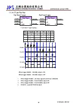
Страница 68: ... Set Clr Q Q DIx 80 DOx 80 DIx 82 DOx 82 The driver contains the general Flip Flop In each Flip Flop needs two input and two output Two input set to DIx 80 and DIx 82 Two outout set to DOx 80 and DOx 82 Relationship When trigger DIx 80 DOx 80 output ON When trigger DIx 82 DOx 80 output OFF DOx 82 opposite DOx 80 output www jps com tw 67 ...

Страница 69: ...Data Ck DIx 81 DIx 83 Truth Table D Type Flip Flop STEP D CK SET CLR Q Q Reset 0 0 0 0 0 1 0 0 0 0 1 1 0 0 1 0 X X 1 0 1 0 X X X 1 0 1 X Don t Care DI x 80 DO x 80 DI x 82 DO x 82 DI x 86 DI x 88 1 When trigger DIx 88 show DIx 86 status to DOx 80 2 When trigger DIx 80 then DOx 80 output ON 3 When trigger DIx 82 then DOx 80 output OFF 4 DOx 82 opposite DOx 80 output www jps com tw 68 ...

Страница 70: ...e Flip Flop STEP Toggle SET CLR Q Q Reset 0 0 0 0 1 0 1 0 1 1 0 0 1 0 1 0 1 0 1 0 1 Q Q DI x 80 DO x 80 DI x 82 DO x 82 DI x 84 When trigger DIx 80 DOx 80 output is ON When trigger DIx 82 DOx 80 output is OFF 1 When trigger DIx 84 all status opposite and show to DOx 80 2 When trigger DIx 80 then DOx 80 output ON 3 When trigger DIx 82 then DOx 80 output OFF 4 DOx 82 opposite DOx 80 output www jps c...

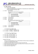
Страница 71: ... 253 Æ T1 time of Timer B z Pr 254 Æ T2 time of Timer B 13 3 2 Timer Group Digital Input z DIx _ Select Æ 60 TIMER A TRIG START input z DIx _ Select Æ 61 TIMER B TRIG START input 13 3 3 Timer Group Digital Output z DOx _ Select Æ 104 Timer A output Q z DOx _ Select Æ 105 Timer A output Q z DOx _ Select Æ 106 Timer B output Q z DOx _ Select Æ 107 Timer B output Q Description of the usage Below sect...

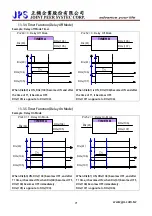
Страница 72: ...f T1 it becomes OFF DOx 107 is opposite to DOx 106 13 3 5 Timer Function Delay On Mode Example Delay On Mode TIMER A DIx 60 DOx 105 DOx 104 Pr 249 1 Delay On Mode TIMER B DIx 61 DOx 107 DOx 106 Pr 252 1 Delay On Mode DIx 60 T1 DOx 105 DOx 104 DIx 61 T1 DOx 107 DOx 106 When DIx 60 ON DOx 104 becomes OFF and after T1 time it becomes ON when DIx 60 becomes OFF DOx 104 becomes OFF immediately DOx 105 ...

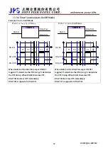
Страница 73: ...1 DOx 107 DOx 106 T2 T1 T1 T2 When DIx 60 is ON DOx 104 output ON OFF toggled T1 determine the ON timing T2 determine the OFF timing When DIx 60 becomes OFF DOx 104 becomes OFF immediately DOx 105 is opposite to DOx 104 When DIx 61 is ON DOx 106 output ON OFF toggled T1 determine the ON timing T2 determine the OFF timing When DIx 61 becomes OFF DOx 106 becomes OFF immediately DOx 107 is opposite t...

Страница 74: ...r 206 the output terminal will be active z DOx _ Select Æ 10 NSPZ Not Speed Zero Speed Pr 206 If the motor s speed Pr 206 the output terminal will be active DOx 9 Speed Pr 206 DOx 10 z DOx _ Select Æ 12 SPA Speed Arrive Pr 19 Actual Speed Set speed Pr 208 When the output terminal function selection mode the function of the SPA Speed Arrive The terminal must start forward or reverse the state and w...

Страница 75: ... the two types function of timer are used to be a speed command source and can be used by selecting the Pr 278 function type 2 13 5 1 Speed Up Down Counter Parameters z Pr 104 Î Speed Up Down Counter start type This parameter defines the start value of Speed Up Down Counter Value Description 0 After power on or reset the Speed Up Down Counter start from 0 1 After power on or reset the Speed Up Dow...

Страница 76: ... volume that will be changed for Speed Up Down Counter in every second When DIx 93 is ON the counter will increase a volume of Pr 107 in every second When DIx 94 is ON the counter will decrease a volume of Pr 107 in every second z Pr 117 Î Up Dn Data Temperary Value This parameter display Up Dn Result value ...

Страница 77: ...ive z DIx _ Select Æ 92 Up Down Buffer Trig DEC If the input is active Decrease the Speed Up Down Counter Pr 106 when be active z DIx _ Select Æ 93 Up Down Buffer Level INC Increase the Speed Up Down Counter by a preset value in Pr 107 every second z DIx _ Select Æ 94 Up Down Buffer Level DEC Decrease the Speed Up Down Counter by a preset value in Pr 107 every second z DIx _ Select Æ 95 Up Down Bu...

Страница 78: ... the DI and DO status of Speed Up Down Counter DIx 91 rpm DIx 92 Pr 106 DIx 90 DIx 95 0 4 Pr 106 3 Pr 106 2 Pr 106 1 Pr 106 Description 1 The start value can be determined by selecting type of Pr 104 to start from 0 or a preloaded value of Pr 105 In here it start from 0 2 When DIx 91 is trigged the output of counter will increase a value of Pr 106 3 When DIx 90 is trigged the output of counter wil...

Страница 79: ...wn Counter DIx 93 rpm DIx 94 Pr 107 DIx 90 DIx 95 0 4 Pr 107 3 Pr 107 2 Pr 107 1 Pr 107 0 1 2 3 4 5 6 7 8 9 10 11 13 14 sec 12 Description 1 The start value can be determined by selecting type of Pr 104 to start from 0 or a preloaded value of Pr 105 In here it start from 0 2 When DIx 93 is trigged the output of counter will increase a value of Pr 107 for every second 3 When DIx 90 is trigged the o...

Страница 80: ...cy of the A B clock is multiplied by 4 times inside the drive NOTE Because the frequency of the A B clock every step of the Rotary Switch will cause the record of Pr 137 to increase 4 or decrease 4 counts z Pr 138 Æ RSW Backup Memory This parameter defines the value that can be the default of the Pr 137 or save the Pr 137 value z Pr 152 Æ RSW Max Data Limit This parameter defines the max limit of ...

Страница 81: ... DI2 204 DI3 205 Æ Set the input definition for Rotary Switch 7 Pr 152 1000 Æ Set max limit value of Rotary Switch 8 Connect the signals A B Store of Rotary Switch to the DIs those were defined by step 6 9 It is necessary to reset the drive to let the changes available 10 Start to run forward and the drive will run in the speed that set by Rotary Switch If the Rotary Switch is see in 500 the speed...

Страница 82: ... I gain P gain z Pr 257 Æ Reserved z Pr 258 Æ Reserved These parameters belong to factory only please do not set z Pr 279 Æ PID CONSTANT Value Belong to ROM This parameter set as constant value can set as PID source or feedback Note This parameter belong to ROM keep value after reset or power off z Pr 280 Æ PID Select Source of SET Value z Pr 281 Æ PID Select Source of PILOT Value value Item descr...

Страница 83: ...w set resolution of Pr 282 produce PID output z Pr 295 Æ PID P Gain2 This parameter set PID P Gain2 Note Normally set method I gain P gain z Pr 296 Æ PID I Gain2 This parameter set PID P Gain2 Note Normally set method I gain P gain z Pr 297 Æ PID Gain Switch Point PID switch point PID gain switch speed Max speed 100 Pr 297 XX YY include XX and YY two sets value XX PID 1 gain switch point YY PID 2 ...

Страница 84: ...e the result PID Error Formule 1 1 dt Error Igain Pgain Error Output PID Example Pr 128 Motor Maximun speed limit 1000 Pr 297 PID switch point 80 20 ÎXX 800 1000 100 80 YY 200 1000 100 20 Pr 255 PID P gain1 500 Pr 256 PID I gain1 50 Pr 295 PID P gain2 100 Pr 296 PID I gain2 10 When actually speed 800rpm main gain PID Gain1 When actually speed 200rpm main gain PID Gain2 When actually speed between ...

Страница 85: ...be in the mode of closed loop 14 2 PCMD Connection Enable Simulated XY input pulse Switch to Speed Command Mode Change XY input pulse direction IRIS Servo Drive DI 2 222 DI 3 223 DI 1 220 DB1 F XY Input 5V Line Driver Input Line speed DB3 M PG Output To Slave To Encoder Enable Pulse Command mode Forward Run DI 5 73 DI 4 224 G24 DB2 M PG Input PCMD www jps com tw 84 ...

Страница 86: ... 450 XY MULTIPLY Pr 451 XY DIVIDE Pr 396 PCMD Position Servo Gain Pr 399 X Y Input Direction Pr 278 10 Pulse CMD Mode Pr 278 0 Speed CMD Mode Pr 456 XY MULTIPLY Execute Value RAM Pr 452 XY Command Type Pr 452 0 XY QEP Type Pr 452 1 X Enable Y CKinput Actual Position CMD www jps com tw 85 ...

Страница 87: ... DIx 223 has same function but it s priority is greater then Pr 398 z Pr 450 Î X Y MUL1 Setting Value ROM z Pr 451 Î X Y DIV1 ROM The above two parameters are used to modify the speed rate for XY input pulse and motor EXP If the input pulses are 10000 and wish motor to move 1024 pulses Pr 399 should be 1024 and Pr 450 should be 10000 z Pr 452 Î X Y Commad Type Can set the format of XY input pulse ...

Страница 88: ...eed volumn is 1000 rpm then the actual feed volumn is 500 rpm for normal condition the value 100 for this parameter is recommended z Pr 455 Î X Y Input Status This parameter displays X Y input status status 0 1 2 3 Note if value 2 mean X signal is on status if value 1 mean Y signal is on status z Pr 456 Î X Y MULx Execute Value RAM XY Multi factor parameter belong to RAM type change this parameter...

Страница 89: ... _ Select Î 222 Reversed definition of function 221 When set ON the control mode is switched to Speed Command mode When set OFF the control mode is switched to Pulse Command mode z DIx _ Select Î 223 Change the direction of XY input pulse When set ON the direction definition of XY input pulse will be changed to the reversed definition of the original The input pulse counts status increased Î decre...

Страница 90: ...ae set to lower value Note After setting Drive needs to be reset After Reset Pr450 value will move to Pr 456 as main PCMD multi executing value 14 5 2 PCMD Start Note In case of avoiding damage please pre excute the process in the condition that motor is not linked to transmit system DI5 73 Forward Run Keep in ON state DI2 222 Switch to Speed Command mode Keep in OFF state DI4 224 Enable Pulse Com...

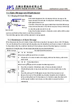
Страница 91: ...ndition by following the setps introduced below with serious maner If still cannot fix the problem after these methods mentioned in here please contact with product agency or maintain department of manufacturer The basicaly maintenance steps are described below Alarm message Description and maintenance A0 no Î No Alarm When showing no presents there is no alarm z If the driver is in normal conditi...

Страница 92: ...ing End presents the auto tuning procedure is finished z This message is used to indicate procedure status and is not an alarm message A0 ES Î Emergency Stop When showing ES presents that there is an external signal to order the driver stop for emergency z Remove the input line of emergency stop signal from the driver s input terminal Under safe condition reset the driver If the alarm message stil...

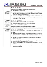
Страница 93: ...he driver will trip and show this message z Check the setting of Pr 215 Electronic Thermo Relay Time is proper or not z Check the setting of Pr 210 Motor Full Load Current Ratio is correct or not z Check the setting of r Pr 211 Motor Exciting Current Ratio is correct or not z Check if the motor is stalled z Check if the load exceeds the rating of motor z Check if the variant of load exceeds the de...

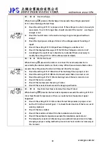
Страница 94: ... in the rating of driver z Check if the setting of Pr 130 Input AC Power Voltage is correct or not z Check if the displayed message of Pr 132 DC Bus Voltage is correct or not A0 OC Î Over Current When showing OC presents the output current exceeds the rating of driver z Check if the type of motor fits in the driver s specification z Check if the rating of motor s fits in the rating of driver z Che...

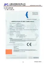
Страница 95: ...16 CE Certificate 16 1 EMC Certificate www jps com tw 94 ...

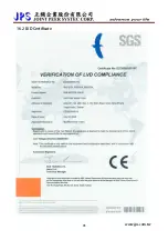
Страница 96: ...16 2 LVD Certificate www jps com tw 95 ...

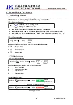
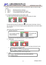
Страница 97: ...tion automatically z After unlock process the display will show unloc after lock process display will show loc 17 1 2 Change mode Press At any status Î By pressing this bottom can enter these different modes sequentially z Monitor mode z Parameter mode z Alarm mode 17 1 3 Monitor mode Select the monitoring item Press or When in Monitor mode Î By using the up down keys can select the monitoring ite...

Страница 98: ...display in the mean time the display will show the present speed and the latest digital will flash to notice that the data is ready to be edit Use fly wheel and the up down keys to edit data z Change the edit position Touch the right or left side of the wheel lightly to change the edit position By using this way can change the edit positon to save the operation time z Edit the value 1 Using the fl...

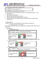
Страница 99: ...ter NOTICE All the operation described below can only work under the condition of the parameter mode or edit mode By using the operation described below can select parameter read value edit value and write the value into parameter 1 Select parameter z Enter select parameter mode Press or to enter select parameter mode or Touch one of the left or right side of wheel lightly to enter select paramete...

Страница 100: ...rm mode then Press or In mode Î messages sequentially ord will be shift by the sequence A0ÆA1ÆA2ÆA3 and the record A0 will be refresh by present status 17 1 6 RESET Function By using Up or Down keys can show A0 A3 alarm z A0 Showing the present alarm message z A1 Showing the alarm message previous than A0 z A2 Showing the alarm message previous than A1 z A3 Showing the alarm message previous than ...

Страница 101: ...s under MON MODE user can monitor some status of Drive like speed RPM frequency RPM and current I and can control motor RUN Forward Reverse and Stop Caution When R PANEL connect to JMD SERIES DRIVER z Neither RPM nor I light up the drive is under CTL MODE the display shows Pr 056 RPM z Only RPM light up the drive is under MON MODE the display shows Pr 056 RPM z Only I light up the drive is under M...

Страница 102: ...parameter number press STOP to change the digital position Step3 Press RD WT to read the value of selected parameter Step4 Press or toverifythevalue press STOP tochangethedigitalposition Step5 Press RD WT to write down the parameter Repeating step 1 5 to verify other parameters 17 2 4 ALARM MODE ALM MODE Press PAR ALM to change between PAR MODE and ALM MODE Continuously press PAR ALM if the displa...

Страница 103: ... button to read parameter value z If this parameter belongs to high word of a Double Word the panel shows as the picture z To change to high word press REV z Press or STOP button to change the value The display is flashing on this time z After deciding the value press RD WT button to write down the value The display stop flashing means the value written down z Parameter belong to Double Word displ...

Страница 104: ...Under this status if the value is negative 1 LED flash Under this status if the value is positive 1 LED lit up Edit status means one of the seven segment displays flashing STOP button works only when parameters are sighed If 1 Led lit up the value is positive If 1 Led flashing the value is negative Parameters belong to signed Double Word high word z Refer to previous chapter read or write paramete...

Страница 105: ...arge Overtime Drive electrical discharge time over protection time A0 OL A0 OL Î Over Load Drive over load time over protection time A0 OH A0 OH Î Over Heat Temperature of heat sink over heat A0 OP A0 OP Î Over Power Voltage over capacitance too high A0 UP A0 UP Î Low Power Voltage over capacitance too low please check the power source A0 OC A0 OC Î Over Current Current output over protection leve...

Страница 106: ...正頻企業股份有限公司 JOINT PEER SYSTEC CORP 222 6F No 266 Sec 3 Pei shen Road Shen Keng shiang Taipei Hsien Taiwan TEL 886 2 26646866 FAX 886 2 26644889 http www jps com tw www jps com tw 105 ...

Отзывы: