Choosing a Mode of Operation
VNET Switch Mode Configurations
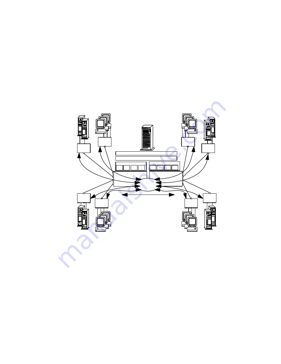
This section describes three configurations using VNET switch
mode.
Configuration 1
Protocol
Port 1 Port 2 Port 3 Port 4
Port 1 Port 2
Port 3 Port 4
System Bus
10BaseT
HUB 5
10BaseT
HUB 7
10BaseT
HUB 8
10BaseT
HUB 6
10BaseT
HUB 4
10BaseT
HUB 2
Net 1
Net 1
Net 1
Net 1
Net 1
Net 1
Net 1
Net 1
LAN Driver
Adapter 1
Adapter 2
Port 1
Port 2
Port 3
Port 4
Port 1
Port 2
Port 3
Port 4
LAN Driver
Virtual Network Layer
10BaseT
HUB 3
VNET
Switch 1
10BaseT
HUB 1
.
.
This illustration shows:
Two PeerMaster adapters (Adapter 1 and Adapter 2) forming a
single VNET.
In this configuration, the adapter provides the functions of a
high-performance network adapter combined with the power of
an Ethernet switching hub.
All segments configured as Network number 1 (Net 1).
Curved arrows indicating the flow of data across ports
connected by the VNET switch.
Chapter 4. Configuring the PeerMaster Adapter
137
Содержание PC Server 520
Страница 1: ...PC Server 520 User s Handbook for PCI Micro Channel IBM...
Страница 86: ...Installation Checklist 70 PC Server 520 User s Handbook for PCI Micro Channel...
Страница 146: ...Using the Mini Configuration Program 130 PC Server 520 User s Handbook for PCI Micro Channel...
Страница 190: ...Using the SCSISelect Utility Program 174 PC Server 520 User s Handbook for PCI Micro Channel...
Страница 385: ...Installing Additional Test Programs 207 CMD 3 Chapter 7 Solving Problems 369...
Страница 438: ...IBM Part Number 78H6336 Printed in U S A May 1996 78H6336...


