


Section V. Parameter Function Table
52
24
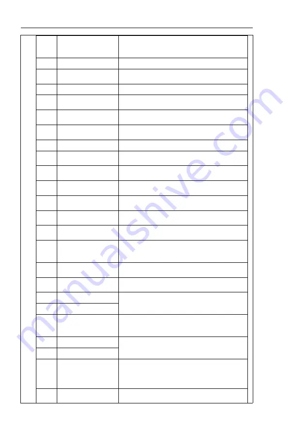
Swing frequency pause
When this terminal command is valid, the inverter maintains
the frequency output of the swing frequency center, and the
swing frequency pauses.
25
Counter input
It is used as input terminal of the counting pulse.
26
Counter reset
When this terminal command is valid, it clears the
counting value of the counter to zero.
27
Length counting input
It is used as pulse input terminal of the length counting.
28
Length counting reset
When this terminal is valid, it clears the length counting to
zero.
29
Torque control forbidden
It prohibits inverter torque control. Inverter enters in
speed control mode.
30
PULSE
frequency
input(Only valid for X5)
X5 is used as pulse input terminal.
31
Reserved
Reserved
32
Immediate DC braking
When this terminal is valid, inverter directly switch to dc
braking state.
33
External default normally
closed input
When the inverter detects that the signal occurs , it will
report “Err15” fault, and stop running.
34
Frequency modification
enable
If the function is valid, inverter Yes not respond to
frequency change until the function turns to be invalid.
35
PID direction reversed
PID and FA.03 set values are set in oppoisite directions
when the terminal is valid.
36
External stop terminal1
It could make inverter stop when in keyboard control.
Equivalent to function of STOP key on the keyboard.
37
Control command
switching terminal 2
It is used to switch control mode between terminal and
communication.
38
PID
integration
suspension
When it is valid, PID integration regulation function pauses,
while PID proportional regulation and differential regulation
function are still valid.
39
Frequency source X and
preset frequency switching
When it is valid, frequency source X is replaced by the
preset frequency F0.08.
40
Frequency source Y and
preset frequency switching
When it is valid, frequency source Y is replaced by the
preset frequency F0.08.
。
41
Motor selection terminal1
It can realize 2 groups of motor parameters switching by 2
combination status of this 2 terminals.For details please
refer to schedule3.
42
Motor selection terminal2
43
PID parameter switching
FA.18=1, the parameter is invalid, PID parameter takes
use of FA.05~FA.07. On the contrary, FA.15~FA.17 are
taken for the use.
44
User-defined fault 1
When user-defined fault 1&2 are valid, inverter alarm fault
number 27= E.USt1 & 28= E.USt2 respectively. Inverter will
handle the fault according to the mode selected by F9.49.
45
User-defined fault 2
46
Speed control/ torque
control switching
It enables control mode to switch between inverter torque
control and speed control. Inverter running in the A0.00
defined mode when the terminal is invalid, and will switch
to another mode when it is valid.
47
Emergency stop
Inverter stops at the fastest speed when the terminal is
valid. Current is set to the current upper limit during this
Содержание HV610C Series
Страница 1: ...HV610C Series Frequency Inverter User Manual HNC Electric Limited ...
Страница 25: ...Section II Installation Wiring 12 2 3 2 Typical wiring of HV610C in Crane applications ...
Страница 29: ...Section II Installation Wiring 16 Control board terminal layout ...
Страница 167: ......
Страница 175: ......


