Section V. Parameter Function Table
44
then accelerate to 80% of motor rated frequency according to F0.17. After keeping the state for a period
of time, then decelerate to stop according to F0.18 and stop tuning.
Before asynchronous complete tuning , users should set motor type and motor nameplate
parameters F1.00~F1.05 as well as encoder type and encoder pulse numbers F1.27
、
F1.28.
Inverter can get 5 motor parameters F1.06~F1.10 as well as AB phase sequence F1.30, vector
control current loop PI parameter F2.13~F2.16 from tuning.
Action description
:
Set F1.37 to 2 and then press RUN button, inverter will carry out asynchronous
complete tuning.
3
:
Asynchronous motor static tuning
It is used for no encoder
5.4 Vector control function group
:
F2.00-F2.22
F2 group function codes are valid for vector control and invalid for V/F control.
Code
Description/Display
Setting Range
Factory
Setting
Change
Limite
F2.00 Speed loop proportional gain1 1~100
30
☆
F2.01 Speed loop integration time1
0.01s~10.00s
0.50s
☆
F2.02 Switching frequency1
0.00~F2.05
5.00Hz
☆
F2.03 Speed loop proportional gain 2 0~100
15
☆
F2.04 Speed loop integration time 2
0.01s~10.00s
1.00s
☆
F2.05 Switching frequency 2
F2.02~maximum frequency
10.00Hz
☆
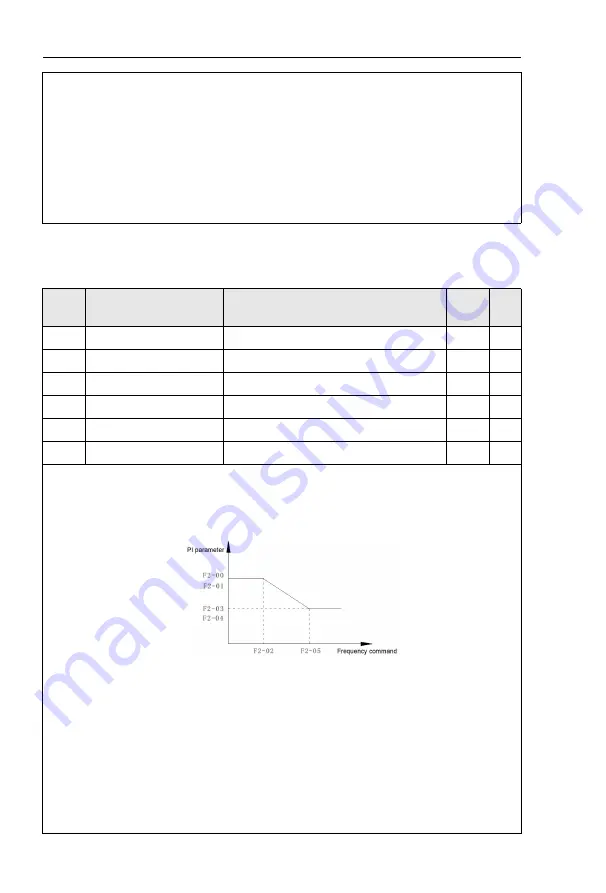
Users could choose different speed loop PI parameters under different running frequency. When
running frequency is less than the switching frequency(F2.02), adjusting parameters for speed loop PI are
F2.00 and F2.01. When running frequency is greater than the switching frequency (F2.02), adjusting
parameters for speed loop PI are F2.03 and F2.04. Speed loop PI parameters between switching
frequency1 and switching frequency2 are two groups of linear switching. As shown in fig.5.2
:
Fig.5-2PI parameter schematic diagram
Users can adjust vector control speed dynamic response characteristics through setting proportional
coefficient and integration time of the speed regulator.
Both increasing proportional gain and reducing integration time can accelerate the speed loop
dynamic response.But excessive proportional gain or insufficient integration time may led to system
oscillation.
Suggestions for regulating method
:
If the factory parameters can not meet the requirements, users can fine-tuning it on the basis of factory
value parameters. First increase the proportional gain to restrain system oscillation,then reduce integration
time so that system has fast response characteristic and smaller overshoot.
Notice
:
Improper PI parameter setting may lead to excessive speed overshoot , even volt age fault
during overshoot drop.
Содержание HV610C Series
Страница 1: ...HV610C Series Frequency Inverter User Manual HNC Electric Limited ...
Страница 25: ...Section II Installation Wiring 12 2 3 2 Typical wiring of HV610C in Crane applications ...
Страница 29: ...Section II Installation Wiring 16 Control board terminal layout ...
Страница 167: ......
Страница 175: ......


