


SECTION 9 –
MAINTENANCE AND STORAGE
9-30
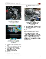
for movement. If plates become
loose, the leg will rock as the
machine starts to move.
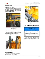
EVEN PRESSURE OF THE TREAD
ADJUST BEARING PLATES IS REQUIRED
FOR PROPER OPERATION.
•
Figure A
- shows correct position of the
tread adjust bearing plates and bolts, as
well as the outer leg.
•
Figure B
- shows the plates when there
is not even torque on each of the tread
adjust bearing bolts.
•
Figure C
- shows a situation in which
there is not enough torque on the tread
adjust bearing bolts.
NOTE: Both Figures B and C will cause the
tread adjust to operate incorrectly, or
not at all.
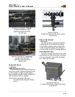
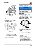
SERVICE - TOE-IN
Step 1 - Phase Steering
Cylinders
The steering cylinders must be phased
before any mechanical adjustments can be
made (cylinder stroke = 8.8”/22.4 cm). When
the cylinders are re-phased, each cylinder
should reach mid-stroke (4.4”/11.2 cm).
Once both cylinders are at 4.4”/11.2 cm, Toe-
In can be set.
To Phase the Steering Cylinders
1. Start the machine.
2. Turn steering wheel to the right or left.
3. When the wheels stop turning, continue
to turn the steering wheel 3 to 4 full revo-
lutions (this will put the cylinders back in
phase with each other).
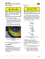
Step 2 - Set Toe-In
Front Wheels
•
.25” (.6 cm) Toe-In per side/0.5” (1.3 cm)
total Toe-In
Rear Wheels
•
0” (0 cm) Toe-In/Out
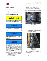
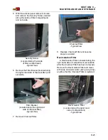
To Set Toe-In
1. Deflate the air bags.
NOTE: Refer to “Air Suspension Exhaust”
provided in the Miscellaneous
Section elsewhere in this manual for
further information.
2. Measure the distance from the ground to
center of wheel hub.
NOTE: All four wheel hubs should measure
the same distance.
3. Mark this distance on the inner edge of
the wheel rim (front and back of each rim
- 8 marks total).
NOTE: All measurements will be taken from
these markings.
4. Visually align the tires from front to rear.
Front Wheels
5. Measure the width between the front
wheels (front W1, rear W2) at the wheel
hub center line and record measure-
ments.
6. Adjust the wheels until the front and rear
measurements are equal (W1=W2).
NOTICE
If hydraulic tread adjust will never be
used, set all bolt torque settings to 50 ft.-
lbs. using the following procedure.
A
B
C
Содержание UpFront STS 16
Страница 3: ...Ladder Fuel Fill 10 21 Tall Crop Package Installation 10 24 Troubleshooting 10 37...
Страница 341: ......


