


Major Inspection — Inspection Procedures
Inspection and Maintenance — GEK 107048
MI-I-5
Note:
The cumulative width of all scratches in circumferential and axial di-
rections should not exceed 0.100 in. (Circumferential or axial pit for-
mations exceeding three in number must be counted as continuous
scratches.) Raised metal may be removed by scraping or lightly polish-
ing the affected area with “Plastic Wool” such as “Scotchbrite.” Dam-
age that exceeds the specified limits requires replacement of the bear-
ing liner.
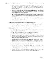
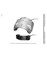
7. If the bearing liner has experienced excessive temperatures, the babbitt will show evidence of
smear and wiping. If the wiped area is less than five percent of the liner lower-half area, the bear-
ing may be reused after re pair of the wiped surface. Larger wiped areas must be repaired by an
approved General Electric Company Repair Facility. Before replacing the liner, the cause of the
wipe must be determined and corrected.
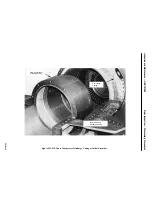
8. Most journal bearings develop polished areas during low speed cranking or coastdown condi-
tions. The polished area is usually found at the bottom centerline of the bearing liner and should
extend along the entire length of the bearing. This type of pattern is normal and should not be
cause for any alarm. If, however, the polished area is found only on one edge of the liner, or if
it appears on the liner upper half, a problem is indicated which must be corrected to prevent even-
tual bearing wipe.
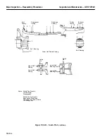
9. Measure journal diameter at two planes, fore and aft. Record these dimensions and the general
condition of the journals on Inspection Form PGS/GT-FF-6116. Roundness and taper are two of
the most critical dimensions associated with a bearing journal. These dimensions are established
with a four point check taken in the vertical and horizontal planes (at 90 degrees to one another)
at both the forward and aft edge of the journal. If the journal diameter is 0.002 in. or more outside
of its drawing tolerance, and, if the liner-to-journal clearance falls outside of the drawing toler-
ances, it may be necessary to remachine the journal. It should be noted that whenever a journal
is remachined, the rotor must be rebalanced. Journal tapers that fall outside of the specified draw-
ing tolerances may also require remachining and rebalancing. Scratches or pits that are not over
0.005 in. deep, pits that are not over 0.100 in. in diameter and pits or scratches that do not extend
axially more than 1/3 of the bearing width, (axial scratches and pit formations must be circumer-
entially at least 45 degrees apart) are acceptable. Raised metal is not allowed.
Note:
The cumulative width of all scratches in circumferential and axial di-
rection should not exceed 0.100 in. (Circumferential or axial in-line pit
formations exceeding three in number must be counted as continuous
scratches.)
Raised metal may be removed by lapping, stoning, or lightly strapping
the entire journal surface. Damage that exceeds the specified limits
may be repaired by an approved General Electric Company repair fa-
cility by skim cutting the journal to a diameter 0.002 in. below drawing
minimum. Deeper imperfections must be repaired by turning the jour-
nal to the next appropriate undersize diameter specified by an ap-
proved General Electric Company repair facility.
10. Clamp the number one (1) and the number two (2) bearing halves together, and make a six point
check for inside diameter. Record all bearing and journal measurements and condition on Inspec-
tion Form PGS/GT-FF-6116. Record all bearing seal clearances and condition on Inspection
Forms PGS/GT-FF-6109 and PGS/GT-FF-6110.
Содержание MS6001B
Страница 2: ...Gas Turbine Inspection and Maintenance GEK 107048 I 2 THIS PAGE INTENTIONALLY LEFT BLANK ...
Страница 4: ...Inspection and Maintenance Note THIS PAGE INTENTIONALLY LEFT BLANK ...
Страница 12: ...Inspection and Maintenance Notes Cautions and Warnings viii THIS PAGE INTENTIONALLY LEFT BLANK ...
Страница 13: ...INSERT TAB INTRODUCTION ...
Страница 14: ......
Страница 25: ...INSERT TAB STANDARD PRACTICES ...
Страница 26: ......
Страница 57: ...Standard Practices Inspection and Maintenance GEK 107048 SP 31 Figure 2 26 Rail Fabrication Hoist ...
Страница 58: ...Inspection and Maintenance GEK 107048 Standard Practices SP 32 Figure 2 27 Pulley Nozzle Segments ...
Страница 59: ...Standard Practices Inspection and Maintenance GEK 107048 SP 33 Figure 2 28 Typical Borescope Kit ...
Страница 60: ...Inspection and Maintenance GEK 107048 Standard Practices SP 34 Figure 2 29 Rail Channel Trolley ...
Страница 61: ...Standard Practices Inspection and Maintenance GEK 107048 SP 35 Figure 2 30 Lifting Beam Inlet Silencer ...
Страница 62: ...Inspection and Maintenance GEK 107048 Standard Practices SP 36 Figure 2 31 Lifting Beam Inlet Transition ...
Страница 63: ...Standard Practices Inspection and Maintenance GEK 107048 SP 37 Figure 2 32 Lifting Beam Inlet Elbow ...
Страница 66: ...Inspection and Maintenance GEK 107048 Standard Practices SP 40 Figure 2 38 Tubing Insert and Male Connector ...
Страница 86: ...Inspection and Maintenance GEK 107048 Standard Practices SP 60 THIS PAGE INTENTIONALLY LEFT BLANK ...
Страница 87: ...INSERT TAB AUXILIARY CONTROLS SYSTEMS MAINTENANCE ...
Страница 88: ......
Страница 90: ...Auxiliary and Controls Systems Maintenance Inspection and Maintenance THIS PAGE INTENTIONALLY LEFT BLANK ...
Страница 104: ...Auxiliary and Controls Systems Maintenance Inspection and Maintenance ACSM 14 THIS PAGE INTENTIONALLY LEFT BLANK ...
Страница 106: ...Inspection and Maintenance Procedures Inspection and Maintenance I 2 THIS PAGE INTENTIONALLY LEFT BLANK ...
Страница 132: ...Inspection and Maintenance Procedures Inspection and Maintenance IMP 26 THIS PAGE INTENTIONALLY LEFT BLANK ...
Страница 133: ...INSERT TAB SCHEDULED TURBINE MAINTENACE ...
Страница 134: ......
Страница 153: ...Scheduled Turbine Maintenance Inspection and Maintenance GEK 107048 STM 19 Figure 4 2 Borescope Light Supply ...
Страница 156: ...Inspection and Maintenance GEK 107048 Scheduled Turbine Maintenance STM 22 Figure 4 5 TV Monitor Presentation ...
Страница 157: ...INSERT TAB COMBUSTION INSPECTION ...
Страница 158: ......
Страница 160: ...Inspection and Maintenance GEK 107048 Combustion Inspection 2 THIS PAGE INTENTIONALLY LEFT BLANK ...
Страница 239: ...INSERT TAB HOT GAS PATH INSPECTION ...
Страница 240: ......
Страница 242: ...Inspection and Maintenance GEK 107048 Hot Gas Path Inspection 2 THIS PAGE INTENTIONALLY LEFT BLANK ...
Страница 313: ...INSERT TAB MAJOR INSPECTION ...
Страница 314: ......
Страница 316: ...Inspection and Maintenance GEK 107048 Major Inspection 2 THIS PAGE INTENTIONALLY LEFT BLANK ...
Страница 350: ...Inspection and Maintenance GEK 107048 Major Inspection Inspection Procedures MI I 8 THIS PAGE INTENTIONALLY LEFT BLANK ...
Страница 363: ...INSERT TAB MAINTENANCE FORMS ...
Страница 364: ......
Страница 370: ...Inspection and Maintenance GEK 107048 Maintenance Forms MF 6 THIS PAGE INTENTIONALLY LEFT BLANK ...