Inspection and Maintenance Procedures
Inspection and Maintenance
IMP–20
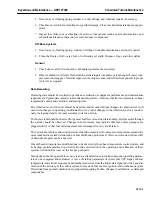
CAUTION
The sensors are polarity sensitive. Reverse polarity will
destroy the detector!!!
1. With the detector amplifier power on, verify base wir-
ing polarity at the sensor junction box by reading 290
VDC (min.) across lead pair.
2. Turn power off and connect the black detector lead to
plus ( + ) and the white lead to minus ( – ).
4. With the system connected, place an ultraviolet source in front of the sensors and check that the in-
ternal relays operate as indicated by using an ohmmeter or equivalent at the contacts. Note that a
paper match flame should be detected at approximately 18 in. (45.7 cm) and the sensor should pro-
vide an orange flickering glow. If the flickering glow persists after removal of the flame, the sensor
has failed and should be replaced. If no flickering glow occurs in the presence of flame, the sensor
may have failed but proper operation of the electronics should be assured.
Scanner Lens
The scanner lens should be cleaned with a dry cloth as often as necessary on a regular schedule. No repair
of any sort should be attempted on the scanner, or switch assembly. If damaged, or defective, it should
be replaced and returned to the factory.
Refer to the Control Specification — Control System Adjustments for testing of flame detectors with
the unit in operation. Refer to the Control Specification for logic signal output explanation.
OVERSPEED PROTECTION SYSTEM (ELECTRONIC)
Magnetic Pickups
The clearances between the OD of the toothed wheel and the tip of the magnetic pickup should be
checked annually and at each removal and installation. The clearances should be within the limits speci-
fied in the Control Arrangement Drawing, Model List Item 0501 or the Device Summary.
Calibration Checks
These calibration checks of the overspeed protection system should be performed annually and after
each major inspection, or at any time wiring has been disconnected.
SPEEDTRONIC CONTROLS AND EQUIPMENT
Control Panel and Power Supply Components
Any indication of corrosion or discoloration, due to heat, should be investigated and the equipment re-
paired or replaced as necessary.
In atmospheres that contain contaminants, such as hydrogen sulfide, sulfuric acid, sulfur dioxide, chlo-
rine, and chlorine dioxide, the relative humidity of the SPEEDTRONIC control panel location should
Содержание MS6001B
Страница 2: ...Gas Turbine Inspection and Maintenance GEK 107048 I 2 THIS PAGE INTENTIONALLY LEFT BLANK ...
Страница 4: ...Inspection and Maintenance Note THIS PAGE INTENTIONALLY LEFT BLANK ...
Страница 12: ...Inspection and Maintenance Notes Cautions and Warnings viii THIS PAGE INTENTIONALLY LEFT BLANK ...
Страница 13: ...INSERT TAB INTRODUCTION ...
Страница 14: ......
Страница 25: ...INSERT TAB STANDARD PRACTICES ...
Страница 26: ......
Страница 57: ...Standard Practices Inspection and Maintenance GEK 107048 SP 31 Figure 2 26 Rail Fabrication Hoist ...
Страница 58: ...Inspection and Maintenance GEK 107048 Standard Practices SP 32 Figure 2 27 Pulley Nozzle Segments ...
Страница 59: ...Standard Practices Inspection and Maintenance GEK 107048 SP 33 Figure 2 28 Typical Borescope Kit ...
Страница 60: ...Inspection and Maintenance GEK 107048 Standard Practices SP 34 Figure 2 29 Rail Channel Trolley ...
Страница 61: ...Standard Practices Inspection and Maintenance GEK 107048 SP 35 Figure 2 30 Lifting Beam Inlet Silencer ...
Страница 62: ...Inspection and Maintenance GEK 107048 Standard Practices SP 36 Figure 2 31 Lifting Beam Inlet Transition ...
Страница 63: ...Standard Practices Inspection and Maintenance GEK 107048 SP 37 Figure 2 32 Lifting Beam Inlet Elbow ...
Страница 66: ...Inspection and Maintenance GEK 107048 Standard Practices SP 40 Figure 2 38 Tubing Insert and Male Connector ...
Страница 86: ...Inspection and Maintenance GEK 107048 Standard Practices SP 60 THIS PAGE INTENTIONALLY LEFT BLANK ...
Страница 87: ...INSERT TAB AUXILIARY CONTROLS SYSTEMS MAINTENANCE ...
Страница 88: ......
Страница 90: ...Auxiliary and Controls Systems Maintenance Inspection and Maintenance THIS PAGE INTENTIONALLY LEFT BLANK ...
Страница 104: ...Auxiliary and Controls Systems Maintenance Inspection and Maintenance ACSM 14 THIS PAGE INTENTIONALLY LEFT BLANK ...
Страница 106: ...Inspection and Maintenance Procedures Inspection and Maintenance I 2 THIS PAGE INTENTIONALLY LEFT BLANK ...
Страница 132: ...Inspection and Maintenance Procedures Inspection and Maintenance IMP 26 THIS PAGE INTENTIONALLY LEFT BLANK ...
Страница 133: ...INSERT TAB SCHEDULED TURBINE MAINTENACE ...
Страница 134: ......
Страница 153: ...Scheduled Turbine Maintenance Inspection and Maintenance GEK 107048 STM 19 Figure 4 2 Borescope Light Supply ...
Страница 156: ...Inspection and Maintenance GEK 107048 Scheduled Turbine Maintenance STM 22 Figure 4 5 TV Monitor Presentation ...
Страница 157: ...INSERT TAB COMBUSTION INSPECTION ...
Страница 158: ......
Страница 160: ...Inspection and Maintenance GEK 107048 Combustion Inspection 2 THIS PAGE INTENTIONALLY LEFT BLANK ...
Страница 239: ...INSERT TAB HOT GAS PATH INSPECTION ...
Страница 240: ......
Страница 242: ...Inspection and Maintenance GEK 107048 Hot Gas Path Inspection 2 THIS PAGE INTENTIONALLY LEFT BLANK ...
Страница 313: ...INSERT TAB MAJOR INSPECTION ...
Страница 314: ......
Страница 316: ...Inspection and Maintenance GEK 107048 Major Inspection 2 THIS PAGE INTENTIONALLY LEFT BLANK ...
Страница 350: ...Inspection and Maintenance GEK 107048 Major Inspection Inspection Procedures MI I 8 THIS PAGE INTENTIONALLY LEFT BLANK ...
Страница 363: ...INSERT TAB MAINTENANCE FORMS ...
Страница 364: ......
Страница 370: ...Inspection and Maintenance GEK 107048 Maintenance Forms MF 6 THIS PAGE INTENTIONALLY LEFT BLANK ...

