Major Inspection — Disassembly Procedures
Inspection and Maintenance — GEK 107048
MI-D-21
Note:
All axial compressor clearances are to be measured with the rotor in
contact with the forward or “normally loaded” face of the thrust
bearing.
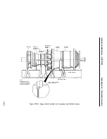
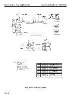
7. Measure and record stator blade tip clearances for all seventeen compressor stages (S1 to S17).
8. Measure and record compressor rotor blade tip clearances for all seventeen compressor stages (R1
to R17).
9. Measure and record exit guide vane stator blade clearances (EGV1 and EGV2).
10. Measure and record the compressor rotor leak off clearances as well as the radial and axial packing
gland clearances (P1, P2, P3 and P4).
11. Measure and record the inlet guide vane and rub ring clearances (X, X1, and X2). Clearances are
referenced on Inspection Form PGS/GT-FF-6108.
Note:
If dirt has been left on compressor blade tips after cleaning during op-
eration and prior to shutdown it may be necessary to hand clean the
blade tips before making clearance checks or proceeding with visual in-
spection. Refer to Gas Turbine Compressor Cleaning in the Standard
Practices section, of this Service Manual.
12. Make visual inspection for compressor blade tip rubs, visible cracks, corrosion, erosion and for-
eign object damage.
13. Report the conditions found on PGS/GT-FF-6107 Inspection Form.
Operation 16 — Perform Hot Gas Path Disassembly Procedures, Operations 11 Through 17
Note:
Refer to the Hot Gas Path Inspection, in this Service Manual for the fol-
lowing disassembly operations.
1. Remove upper half first stage nozzle.
2. Remove lower half first stage nozzle.
3. Remove lower half second and third stage nozzle radial retaining pins.
4. Remove lower half second and third stage nozzle segments.
Operation 17 — How to Remove Upper Half Number One and Two Bearing Housings
Note:
The upper half of number one bearing housing weighs approximately
560 pounds and the upper half of number two bearing weighs approxi-
mately 380 pounds.
Number One Bearing
Note:
On some units the upper half number one bearing liner will be as-
sembled to the upper half housing and will be removed with the hous-
Содержание MS6001B
Страница 2: ...Gas Turbine Inspection and Maintenance GEK 107048 I 2 THIS PAGE INTENTIONALLY LEFT BLANK ...
Страница 4: ...Inspection and Maintenance Note THIS PAGE INTENTIONALLY LEFT BLANK ...
Страница 12: ...Inspection and Maintenance Notes Cautions and Warnings viii THIS PAGE INTENTIONALLY LEFT BLANK ...
Страница 13: ...INSERT TAB INTRODUCTION ...
Страница 14: ......
Страница 25: ...INSERT TAB STANDARD PRACTICES ...
Страница 26: ......
Страница 57: ...Standard Practices Inspection and Maintenance GEK 107048 SP 31 Figure 2 26 Rail Fabrication Hoist ...
Страница 58: ...Inspection and Maintenance GEK 107048 Standard Practices SP 32 Figure 2 27 Pulley Nozzle Segments ...
Страница 59: ...Standard Practices Inspection and Maintenance GEK 107048 SP 33 Figure 2 28 Typical Borescope Kit ...
Страница 60: ...Inspection and Maintenance GEK 107048 Standard Practices SP 34 Figure 2 29 Rail Channel Trolley ...
Страница 61: ...Standard Practices Inspection and Maintenance GEK 107048 SP 35 Figure 2 30 Lifting Beam Inlet Silencer ...
Страница 62: ...Inspection and Maintenance GEK 107048 Standard Practices SP 36 Figure 2 31 Lifting Beam Inlet Transition ...
Страница 63: ...Standard Practices Inspection and Maintenance GEK 107048 SP 37 Figure 2 32 Lifting Beam Inlet Elbow ...
Страница 66: ...Inspection and Maintenance GEK 107048 Standard Practices SP 40 Figure 2 38 Tubing Insert and Male Connector ...
Страница 86: ...Inspection and Maintenance GEK 107048 Standard Practices SP 60 THIS PAGE INTENTIONALLY LEFT BLANK ...
Страница 87: ...INSERT TAB AUXILIARY CONTROLS SYSTEMS MAINTENANCE ...
Страница 88: ......
Страница 90: ...Auxiliary and Controls Systems Maintenance Inspection and Maintenance THIS PAGE INTENTIONALLY LEFT BLANK ...
Страница 104: ...Auxiliary and Controls Systems Maintenance Inspection and Maintenance ACSM 14 THIS PAGE INTENTIONALLY LEFT BLANK ...
Страница 106: ...Inspection and Maintenance Procedures Inspection and Maintenance I 2 THIS PAGE INTENTIONALLY LEFT BLANK ...
Страница 132: ...Inspection and Maintenance Procedures Inspection and Maintenance IMP 26 THIS PAGE INTENTIONALLY LEFT BLANK ...
Страница 133: ...INSERT TAB SCHEDULED TURBINE MAINTENACE ...
Страница 134: ......
Страница 153: ...Scheduled Turbine Maintenance Inspection and Maintenance GEK 107048 STM 19 Figure 4 2 Borescope Light Supply ...
Страница 156: ...Inspection and Maintenance GEK 107048 Scheduled Turbine Maintenance STM 22 Figure 4 5 TV Monitor Presentation ...
Страница 157: ...INSERT TAB COMBUSTION INSPECTION ...
Страница 158: ......
Страница 160: ...Inspection and Maintenance GEK 107048 Combustion Inspection 2 THIS PAGE INTENTIONALLY LEFT BLANK ...
Страница 239: ...INSERT TAB HOT GAS PATH INSPECTION ...
Страница 240: ......
Страница 242: ...Inspection and Maintenance GEK 107048 Hot Gas Path Inspection 2 THIS PAGE INTENTIONALLY LEFT BLANK ...
Страница 313: ...INSERT TAB MAJOR INSPECTION ...
Страница 314: ......
Страница 316: ...Inspection and Maintenance GEK 107048 Major Inspection 2 THIS PAGE INTENTIONALLY LEFT BLANK ...
Страница 350: ...Inspection and Maintenance GEK 107048 Major Inspection Inspection Procedures MI I 8 THIS PAGE INTENTIONALLY LEFT BLANK ...
Страница 363: ...INSERT TAB MAINTENANCE FORMS ...
Страница 364: ......
Страница 370: ...Inspection and Maintenance GEK 107048 Maintenance Forms MF 6 THIS PAGE INTENTIONALLY LEFT BLANK ...

