


Hot Gas Path Inspection — Disassembly Procedures
Inspection and Maintenance — GEK 107048
HGP-D-25
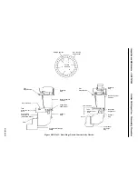
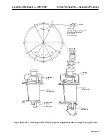
Operation 18 — How to Remove Upper Half Second and Third Stage Nozzle Radial Retaining
Pins
Note:
The second stage nozzle radial retaining pins are secured to the turbine
casing by threaded plugs which are screwed into the casing, each plug
is staked in two places.
The third stage nozzle radial retaining pins are secured in position by
plates secured to the turbine casing by hex head bolts with lockplates.
The retaining pins are drilled and tapped so that a bolt can be screwed
into the head and a puller can be used to extract the retaining pins.
1. Remove the second stage nozzle threaded plugs and the retaining pins.
2. Remove the holding plates which secure the third stage nozzle radial retaining pins and remove
the retaining pins. If pins are not stamped for location, stamp them.
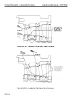
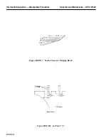
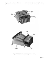
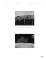
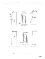
Operation 19 — How to Remove Upper Half Second and Third Stage Nozzle Segments
1. Each nozzle segment can be removed from the turbine casing by “rolling” it out individually on
its outer sidewall forward and aft hook fits. Each diaphragm segment is removed along with its
adjacent nozzle segment as one piece. Mark each segment per Inspection Form PGS/GT-FF-6099
and 6102 numbering sequence.
Note:
The turbine casing should be on its forward vertical flange for nozzle
segment removal.
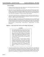
CAUTION
At all points where the segment and pulling cable come in
contact, there should be ample padding to distribute the
load and protect the partition surfaces. wood, rubber or
padded steel plates can be used.
2. Tools required for nozzle removal are: pulley assembly, one-ton “come-along,” and 0.375 in. di-
ameter wire rope or fiber sling.
3. Commence by attaching the cable to the nozzle segment closest to the horizontal joint. Remove
the nozzle segment using a one-ton “come-along”.
4. Attach the one-ton “come-along” to a suitable support point. Continue on the remaining nozzle
segments and remove in a similar manner, as described per Operation 15, step 3 thru 8.
Содержание MS6001B
Страница 2: ...Gas Turbine Inspection and Maintenance GEK 107048 I 2 THIS PAGE INTENTIONALLY LEFT BLANK ...
Страница 4: ...Inspection and Maintenance Note THIS PAGE INTENTIONALLY LEFT BLANK ...
Страница 12: ...Inspection and Maintenance Notes Cautions and Warnings viii THIS PAGE INTENTIONALLY LEFT BLANK ...
Страница 13: ...INSERT TAB INTRODUCTION ...
Страница 14: ......
Страница 25: ...INSERT TAB STANDARD PRACTICES ...
Страница 26: ......
Страница 57: ...Standard Practices Inspection and Maintenance GEK 107048 SP 31 Figure 2 26 Rail Fabrication Hoist ...
Страница 58: ...Inspection and Maintenance GEK 107048 Standard Practices SP 32 Figure 2 27 Pulley Nozzle Segments ...
Страница 59: ...Standard Practices Inspection and Maintenance GEK 107048 SP 33 Figure 2 28 Typical Borescope Kit ...
Страница 60: ...Inspection and Maintenance GEK 107048 Standard Practices SP 34 Figure 2 29 Rail Channel Trolley ...
Страница 61: ...Standard Practices Inspection and Maintenance GEK 107048 SP 35 Figure 2 30 Lifting Beam Inlet Silencer ...
Страница 62: ...Inspection and Maintenance GEK 107048 Standard Practices SP 36 Figure 2 31 Lifting Beam Inlet Transition ...
Страница 63: ...Standard Practices Inspection and Maintenance GEK 107048 SP 37 Figure 2 32 Lifting Beam Inlet Elbow ...
Страница 66: ...Inspection and Maintenance GEK 107048 Standard Practices SP 40 Figure 2 38 Tubing Insert and Male Connector ...
Страница 86: ...Inspection and Maintenance GEK 107048 Standard Practices SP 60 THIS PAGE INTENTIONALLY LEFT BLANK ...
Страница 87: ...INSERT TAB AUXILIARY CONTROLS SYSTEMS MAINTENANCE ...
Страница 88: ......
Страница 90: ...Auxiliary and Controls Systems Maintenance Inspection and Maintenance THIS PAGE INTENTIONALLY LEFT BLANK ...
Страница 104: ...Auxiliary and Controls Systems Maintenance Inspection and Maintenance ACSM 14 THIS PAGE INTENTIONALLY LEFT BLANK ...
Страница 106: ...Inspection and Maintenance Procedures Inspection and Maintenance I 2 THIS PAGE INTENTIONALLY LEFT BLANK ...
Страница 132: ...Inspection and Maintenance Procedures Inspection and Maintenance IMP 26 THIS PAGE INTENTIONALLY LEFT BLANK ...
Страница 133: ...INSERT TAB SCHEDULED TURBINE MAINTENACE ...
Страница 134: ......
Страница 153: ...Scheduled Turbine Maintenance Inspection and Maintenance GEK 107048 STM 19 Figure 4 2 Borescope Light Supply ...
Страница 156: ...Inspection and Maintenance GEK 107048 Scheduled Turbine Maintenance STM 22 Figure 4 5 TV Monitor Presentation ...
Страница 157: ...INSERT TAB COMBUSTION INSPECTION ...
Страница 158: ......
Страница 160: ...Inspection and Maintenance GEK 107048 Combustion Inspection 2 THIS PAGE INTENTIONALLY LEFT BLANK ...
Страница 239: ...INSERT TAB HOT GAS PATH INSPECTION ...
Страница 240: ......
Страница 242: ...Inspection and Maintenance GEK 107048 Hot Gas Path Inspection 2 THIS PAGE INTENTIONALLY LEFT BLANK ...
Страница 313: ...INSERT TAB MAJOR INSPECTION ...
Страница 314: ......
Страница 316: ...Inspection and Maintenance GEK 107048 Major Inspection 2 THIS PAGE INTENTIONALLY LEFT BLANK ...
Страница 350: ...Inspection and Maintenance GEK 107048 Major Inspection Inspection Procedures MI I 8 THIS PAGE INTENTIONALLY LEFT BLANK ...
Страница 363: ...INSERT TAB MAINTENANCE FORMS ...
Страница 364: ......
Страница 370: ...Inspection and Maintenance GEK 107048 Maintenance Forms MF 6 THIS PAGE INTENTIONALLY LEFT BLANK ...