Hot Gas Path Inspection — Reassembly Procedures
Inspection and Maintenance — GEK 107048
HGP-R-7
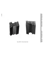
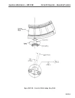
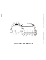
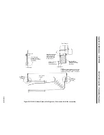
seal strip with the notch facing in. Appropriately stake both seals. See Figures HGP-R.3 and
HGP-R.4.
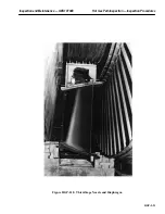
4. Lift the nozzle and diaphragm segment on its hook fit and slide it along to its proper position.
Install nozzle segments from each horizontal joint to the center of the casing. For those nozzle
segments with thermocouple tubes protruding, insure that enough clearance is available to allow
the segments to be rolled in without damaging the tubes. Each segment and diaphragm weighs
approximately 35 pounds.
Note:
Nozzle segment radial locating pins should be installed after each seg-
ment is moved into position.
5. Apply a light coat of anti-seize compound to all radial retaining pins.
Note:
Prior to installing the radial retaining pin threaded access plugs, clean
the plug threads in the retaining pin hole. This will assist in making
reassembly of access plug easier.
6. Install the retaining pins as each nozzle segment is installed, where plugs are used to hold the re-
taining pins install the access plug so that it just bottoms on the retaining pin. Tighten the access
plug against the retaining pin and stake each plug at four (4) places on the edge of the threads.
7. Where pins are secured in place by holding plates, lockplates are to be used to lock the hex head
bolts.
Operation 3 — How to Install Wheelspace Thermocouples in Lower Half Second and Third
Stage Nozzle Segments
Note:
The removable type thermocouples are located in segments 10 and 15
in the second stage nozzle and segments 11 and 14 in the third stage
nozzle. There are two thermocouples per segment.
Refer to the second and third stage nozzle arrangement drawings in the
Parts Lists and Drawings Volume of this Service Manual for details if
needed.
1. Prior to installing the wheelspace thermocouples, test the thermocouples to insure they are opera-
tional. This can be done by applying a small amount of heat to the tip and reading the output on
a temperature meter.
Note:
The assembled length of the engaged portion of the thermocouple is
stamped on the turbine casing adjacent to the thermocouple tubing in-
stallation hole. This dimension may be used for reference when install-
ing the thermocouples. The reference dimension is from the top swage-
lok ferrell to the tip of the thermocouple.
2. Install the wheelspace thermocouples through the installation tubing in the turbine casing into
the second stage nozzle segment numbers 10 and 15 (two per segment).
3. Install the wheelspace thermocouples through the installation tubing in the turbine casing into
the third stage nozzle segment numbers 11 and 14 (two per segment).
Содержание MS6001B
Страница 2: ...Gas Turbine Inspection and Maintenance GEK 107048 I 2 THIS PAGE INTENTIONALLY LEFT BLANK ...
Страница 4: ...Inspection and Maintenance Note THIS PAGE INTENTIONALLY LEFT BLANK ...
Страница 12: ...Inspection and Maintenance Notes Cautions and Warnings viii THIS PAGE INTENTIONALLY LEFT BLANK ...
Страница 13: ...INSERT TAB INTRODUCTION ...
Страница 14: ......
Страница 25: ...INSERT TAB STANDARD PRACTICES ...
Страница 26: ......
Страница 57: ...Standard Practices Inspection and Maintenance GEK 107048 SP 31 Figure 2 26 Rail Fabrication Hoist ...
Страница 58: ...Inspection and Maintenance GEK 107048 Standard Practices SP 32 Figure 2 27 Pulley Nozzle Segments ...
Страница 59: ...Standard Practices Inspection and Maintenance GEK 107048 SP 33 Figure 2 28 Typical Borescope Kit ...
Страница 60: ...Inspection and Maintenance GEK 107048 Standard Practices SP 34 Figure 2 29 Rail Channel Trolley ...
Страница 61: ...Standard Practices Inspection and Maintenance GEK 107048 SP 35 Figure 2 30 Lifting Beam Inlet Silencer ...
Страница 62: ...Inspection and Maintenance GEK 107048 Standard Practices SP 36 Figure 2 31 Lifting Beam Inlet Transition ...
Страница 63: ...Standard Practices Inspection and Maintenance GEK 107048 SP 37 Figure 2 32 Lifting Beam Inlet Elbow ...
Страница 66: ...Inspection and Maintenance GEK 107048 Standard Practices SP 40 Figure 2 38 Tubing Insert and Male Connector ...
Страница 86: ...Inspection and Maintenance GEK 107048 Standard Practices SP 60 THIS PAGE INTENTIONALLY LEFT BLANK ...
Страница 87: ...INSERT TAB AUXILIARY CONTROLS SYSTEMS MAINTENANCE ...
Страница 88: ......
Страница 90: ...Auxiliary and Controls Systems Maintenance Inspection and Maintenance THIS PAGE INTENTIONALLY LEFT BLANK ...
Страница 104: ...Auxiliary and Controls Systems Maintenance Inspection and Maintenance ACSM 14 THIS PAGE INTENTIONALLY LEFT BLANK ...
Страница 106: ...Inspection and Maintenance Procedures Inspection and Maintenance I 2 THIS PAGE INTENTIONALLY LEFT BLANK ...
Страница 132: ...Inspection and Maintenance Procedures Inspection and Maintenance IMP 26 THIS PAGE INTENTIONALLY LEFT BLANK ...
Страница 133: ...INSERT TAB SCHEDULED TURBINE MAINTENACE ...
Страница 134: ......
Страница 153: ...Scheduled Turbine Maintenance Inspection and Maintenance GEK 107048 STM 19 Figure 4 2 Borescope Light Supply ...
Страница 156: ...Inspection and Maintenance GEK 107048 Scheduled Turbine Maintenance STM 22 Figure 4 5 TV Monitor Presentation ...
Страница 157: ...INSERT TAB COMBUSTION INSPECTION ...
Страница 158: ......
Страница 160: ...Inspection and Maintenance GEK 107048 Combustion Inspection 2 THIS PAGE INTENTIONALLY LEFT BLANK ...
Страница 239: ...INSERT TAB HOT GAS PATH INSPECTION ...
Страница 240: ......
Страница 242: ...Inspection and Maintenance GEK 107048 Hot Gas Path Inspection 2 THIS PAGE INTENTIONALLY LEFT BLANK ...
Страница 313: ...INSERT TAB MAJOR INSPECTION ...
Страница 314: ......
Страница 316: ...Inspection and Maintenance GEK 107048 Major Inspection 2 THIS PAGE INTENTIONALLY LEFT BLANK ...
Страница 350: ...Inspection and Maintenance GEK 107048 Major Inspection Inspection Procedures MI I 8 THIS PAGE INTENTIONALLY LEFT BLANK ...
Страница 363: ...INSERT TAB MAINTENANCE FORMS ...
Страница 364: ......
Страница 370: ...Inspection and Maintenance GEK 107048 Maintenance Forms MF 6 THIS PAGE INTENTIONALLY LEFT BLANK ...


