Major Inspection — Disassembly Procedures
Inspection and Maintenance — GEK 107048
MI-D-3
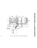
d. The indicator must be placed in such manner to permit face readings to be taken without being
affected by end float (thrust) of the accessory gear shaft when turning the shaft.
e. Rotate the accessory gear coupling with the alignment fixture and dial indicator attached until
indicator is aligned on the top vertical face mark. Set dial indicator to read zero “0.”
f. Rotate the accessory gear coupling (and alignment fixture) through one full revolution (360
°
)
take readings at each face mark (90
°
). Record the dial indicator readings.
Note:
All readings must repeat three consecutive times to be considered accu-
rate.
The indicators should return to “0” (corrected reading of zero for the
face and rim indicators) when returning to the top end of the vertical
mark. If they do not, check tightness of set-up and repeat readings. Re-
fer to the Basic Alignment Instructions (Field) in the Reference Draw-
ings section of this Service Manual.
g. Place dial indicator to read from the fixture to the rim of the turbine coupling flange.
h. Take rim readings in the same manner, except that no correction is necessary for axial move-
ment of the shaft. Record all readings on Inspection Form PGS/GT-FF-6115.
Operation 2 — Perform Combustion Inspection Disassembly Operations No. 1 Through No. 15
CAUTION
Before proceeding with a combustion inspection ensure
that the gas turbine electrical power is tagged-out; CO
2
system is deactivated, liquid fuel system is purged, deacti-
vated and/or the gas supply is blanked off. See Standard
Practices section, in this Service Manual.
Note:
Refer to the Combustion Inspection section of this Service Manual for
the following disassembly operations.
1. Prepare turbine compartment roof for removal.
2. Remove turbine compartment roof and side panels.
3. Remove cooling water lines from flame detectors.
4. Remove the flame detectors.
5. Remove primary gas fuel lines (if applicable).
Note:
In addition to the gas fuel lines to the fuel nozzles, unbolt and remove
the upper half gas manifold pipe also.
6. Remove transfer fuel gas lines.
Содержание MS6001B
Страница 2: ...Gas Turbine Inspection and Maintenance GEK 107048 I 2 THIS PAGE INTENTIONALLY LEFT BLANK ...
Страница 4: ...Inspection and Maintenance Note THIS PAGE INTENTIONALLY LEFT BLANK ...
Страница 12: ...Inspection and Maintenance Notes Cautions and Warnings viii THIS PAGE INTENTIONALLY LEFT BLANK ...
Страница 13: ...INSERT TAB INTRODUCTION ...
Страница 14: ......
Страница 25: ...INSERT TAB STANDARD PRACTICES ...
Страница 26: ......
Страница 57: ...Standard Practices Inspection and Maintenance GEK 107048 SP 31 Figure 2 26 Rail Fabrication Hoist ...
Страница 58: ...Inspection and Maintenance GEK 107048 Standard Practices SP 32 Figure 2 27 Pulley Nozzle Segments ...
Страница 59: ...Standard Practices Inspection and Maintenance GEK 107048 SP 33 Figure 2 28 Typical Borescope Kit ...
Страница 60: ...Inspection and Maintenance GEK 107048 Standard Practices SP 34 Figure 2 29 Rail Channel Trolley ...
Страница 61: ...Standard Practices Inspection and Maintenance GEK 107048 SP 35 Figure 2 30 Lifting Beam Inlet Silencer ...
Страница 62: ...Inspection and Maintenance GEK 107048 Standard Practices SP 36 Figure 2 31 Lifting Beam Inlet Transition ...
Страница 63: ...Standard Practices Inspection and Maintenance GEK 107048 SP 37 Figure 2 32 Lifting Beam Inlet Elbow ...
Страница 66: ...Inspection and Maintenance GEK 107048 Standard Practices SP 40 Figure 2 38 Tubing Insert and Male Connector ...
Страница 86: ...Inspection and Maintenance GEK 107048 Standard Practices SP 60 THIS PAGE INTENTIONALLY LEFT BLANK ...
Страница 87: ...INSERT TAB AUXILIARY CONTROLS SYSTEMS MAINTENANCE ...
Страница 88: ......
Страница 90: ...Auxiliary and Controls Systems Maintenance Inspection and Maintenance THIS PAGE INTENTIONALLY LEFT BLANK ...
Страница 104: ...Auxiliary and Controls Systems Maintenance Inspection and Maintenance ACSM 14 THIS PAGE INTENTIONALLY LEFT BLANK ...
Страница 106: ...Inspection and Maintenance Procedures Inspection and Maintenance I 2 THIS PAGE INTENTIONALLY LEFT BLANK ...
Страница 132: ...Inspection and Maintenance Procedures Inspection and Maintenance IMP 26 THIS PAGE INTENTIONALLY LEFT BLANK ...
Страница 133: ...INSERT TAB SCHEDULED TURBINE MAINTENACE ...
Страница 134: ......
Страница 153: ...Scheduled Turbine Maintenance Inspection and Maintenance GEK 107048 STM 19 Figure 4 2 Borescope Light Supply ...
Страница 156: ...Inspection and Maintenance GEK 107048 Scheduled Turbine Maintenance STM 22 Figure 4 5 TV Monitor Presentation ...
Страница 157: ...INSERT TAB COMBUSTION INSPECTION ...
Страница 158: ......
Страница 160: ...Inspection and Maintenance GEK 107048 Combustion Inspection 2 THIS PAGE INTENTIONALLY LEFT BLANK ...
Страница 239: ...INSERT TAB HOT GAS PATH INSPECTION ...
Страница 240: ......
Страница 242: ...Inspection and Maintenance GEK 107048 Hot Gas Path Inspection 2 THIS PAGE INTENTIONALLY LEFT BLANK ...
Страница 313: ...INSERT TAB MAJOR INSPECTION ...
Страница 314: ......
Страница 316: ...Inspection and Maintenance GEK 107048 Major Inspection 2 THIS PAGE INTENTIONALLY LEFT BLANK ...
Страница 350: ...Inspection and Maintenance GEK 107048 Major Inspection Inspection Procedures MI I 8 THIS PAGE INTENTIONALLY LEFT BLANK ...
Страница 363: ...INSERT TAB MAINTENANCE FORMS ...
Страница 364: ......
Страница 370: ...Inspection and Maintenance GEK 107048 Maintenance Forms MF 6 THIS PAGE INTENTIONALLY LEFT BLANK ...


