Combustion Inspection — Disassembly Procedures
Inspection and Maintenance — GEK 107048
CI-D-19
**WARNING**
Each combustion outer casing weighs approximately
550 pounds and should be rigged accordingly to sup-
port this weight prior to start of disassembly of the out-
er combustion casings.
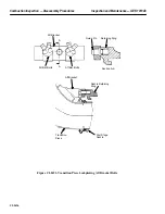
1. Starting with the number 10 combustion casing, rig the casing to the lifting means to support the
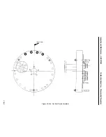
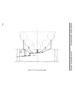
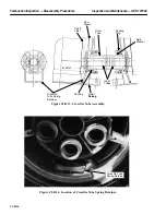
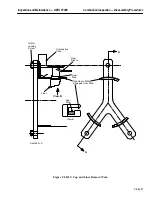
weight. Unbolt the casing from the compressor discharge casing bulkhead. See Figure CI-D.18.
2. Carefully, using the rigging attached, work the combustion casing outward until the flow sleeve
clears the bulkhead. Lift the casing clear of the unit.
3. Set and block the outer casing on wood or heavy cardboard so that no damage is done to the flow
sleeve.
4. Repeat step 2, 3 and 4 for combustion casings 1, 2, 3, 7, 8 and 9.
5. Rig number 4 combustion casing to the lifting means. Attach a comealong to the casing to act as
a restraint to keep the casing from swinging when it clears the compressor discharge casing bulk-
head.
6. Unbolt the casing from the compressor discharge bulkhead and using the rigging attached, care-
fully work the combustion casing outward until the flow sleeve clears the bulkhead. Lift the cas-
ing clear of the unit.
7. Set and block the outer casing on wood or heavy cardboard so that no damage is done to the flow
sleeve.
8. Repeat steps 6, 7 and 8 for combustion casings number 5 and 6.
9. Remove and discard all used gaskets.
10. Clean all hardware and mating flange surfaces. Bag and identify bolting for reassembly.
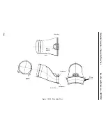
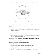
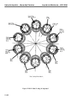
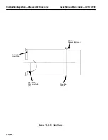
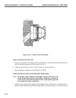
11. Remove the 4 machine screws locating the flow sleeve in the outer casing. See Figure CI-D.19.
12. Slide the flow sleeve aft until it clears the outer casing.
Operation 16 — How to Remove the Transition Pieces
Note:
Before disassembling the transition pieces, clearance measurements
may be taken between the transition piece face and the first stage
nozzle. These measurements, if taken, can be recorded on form PGS/
GT-FF-6408. A special go — no/go gauge is available for this gap mea-
surement.
Note:
Depending on which turbine casing access hand hole ports are avail-
able, (see Operation 18) the first transition piece to be removed can be
Содержание MS6001B
Страница 2: ...Gas Turbine Inspection and Maintenance GEK 107048 I 2 THIS PAGE INTENTIONALLY LEFT BLANK ...
Страница 4: ...Inspection and Maintenance Note THIS PAGE INTENTIONALLY LEFT BLANK ...
Страница 12: ...Inspection and Maintenance Notes Cautions and Warnings viii THIS PAGE INTENTIONALLY LEFT BLANK ...
Страница 13: ...INSERT TAB INTRODUCTION ...
Страница 14: ......
Страница 25: ...INSERT TAB STANDARD PRACTICES ...
Страница 26: ......
Страница 57: ...Standard Practices Inspection and Maintenance GEK 107048 SP 31 Figure 2 26 Rail Fabrication Hoist ...
Страница 58: ...Inspection and Maintenance GEK 107048 Standard Practices SP 32 Figure 2 27 Pulley Nozzle Segments ...
Страница 59: ...Standard Practices Inspection and Maintenance GEK 107048 SP 33 Figure 2 28 Typical Borescope Kit ...
Страница 60: ...Inspection and Maintenance GEK 107048 Standard Practices SP 34 Figure 2 29 Rail Channel Trolley ...
Страница 61: ...Standard Practices Inspection and Maintenance GEK 107048 SP 35 Figure 2 30 Lifting Beam Inlet Silencer ...
Страница 62: ...Inspection and Maintenance GEK 107048 Standard Practices SP 36 Figure 2 31 Lifting Beam Inlet Transition ...
Страница 63: ...Standard Practices Inspection and Maintenance GEK 107048 SP 37 Figure 2 32 Lifting Beam Inlet Elbow ...
Страница 66: ...Inspection and Maintenance GEK 107048 Standard Practices SP 40 Figure 2 38 Tubing Insert and Male Connector ...
Страница 86: ...Inspection and Maintenance GEK 107048 Standard Practices SP 60 THIS PAGE INTENTIONALLY LEFT BLANK ...
Страница 87: ...INSERT TAB AUXILIARY CONTROLS SYSTEMS MAINTENANCE ...
Страница 88: ......
Страница 90: ...Auxiliary and Controls Systems Maintenance Inspection and Maintenance THIS PAGE INTENTIONALLY LEFT BLANK ...
Страница 104: ...Auxiliary and Controls Systems Maintenance Inspection and Maintenance ACSM 14 THIS PAGE INTENTIONALLY LEFT BLANK ...
Страница 106: ...Inspection and Maintenance Procedures Inspection and Maintenance I 2 THIS PAGE INTENTIONALLY LEFT BLANK ...
Страница 132: ...Inspection and Maintenance Procedures Inspection and Maintenance IMP 26 THIS PAGE INTENTIONALLY LEFT BLANK ...
Страница 133: ...INSERT TAB SCHEDULED TURBINE MAINTENACE ...
Страница 134: ......
Страница 153: ...Scheduled Turbine Maintenance Inspection and Maintenance GEK 107048 STM 19 Figure 4 2 Borescope Light Supply ...
Страница 156: ...Inspection and Maintenance GEK 107048 Scheduled Turbine Maintenance STM 22 Figure 4 5 TV Monitor Presentation ...
Страница 157: ...INSERT TAB COMBUSTION INSPECTION ...
Страница 158: ......
Страница 160: ...Inspection and Maintenance GEK 107048 Combustion Inspection 2 THIS PAGE INTENTIONALLY LEFT BLANK ...
Страница 239: ...INSERT TAB HOT GAS PATH INSPECTION ...
Страница 240: ......
Страница 242: ...Inspection and Maintenance GEK 107048 Hot Gas Path Inspection 2 THIS PAGE INTENTIONALLY LEFT BLANK ...
Страница 313: ...INSERT TAB MAJOR INSPECTION ...
Страница 314: ......
Страница 316: ...Inspection and Maintenance GEK 107048 Major Inspection 2 THIS PAGE INTENTIONALLY LEFT BLANK ...
Страница 350: ...Inspection and Maintenance GEK 107048 Major Inspection Inspection Procedures MI I 8 THIS PAGE INTENTIONALLY LEFT BLANK ...
Страница 363: ...INSERT TAB MAINTENANCE FORMS ...
Страница 364: ......
Страница 370: ...Inspection and Maintenance GEK 107048 Maintenance Forms MF 6 THIS PAGE INTENTIONALLY LEFT BLANK ...

