Inspection and Maintenance — GEK 107048
Hot Gas Path Inspection — Disassembly Procedures
HGP-D-20
Use the disassembly procedure applicable to your units configuration.
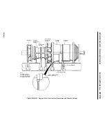
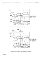
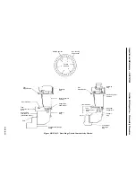
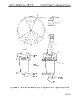
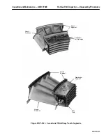
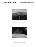
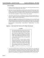
See Figure HGP-D.12.
1. Remove the horizontal joint bolting and clamps from first stage nozzle. Do not remove the joint
dowels. Identify horizontal clamp for left and right side.
2. Carefully lift the top half of the first stage nozzle using a chain fall. Pay special attention to the
support pad seal between nozzle and support ring. The support pad seals must slide out of the
inner support ring. See Figure HGP-D.12.
3. Clean the support pad seal area, and check for and remove any burrs on edges of support pad seal
grooves and tongues.
4. Set the nozzle flat on a piece of plywood or equivalent to protect it from damage.
Operation 12 — How to Remove Upper Half First Stage Nozzle (With Tangential Support Pin)
1. Remove horizontal joint bolting and clamps from first-stage nozzle.
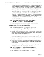
2. Remove the tangential support pin bolts and retainer plates. Discard bolts and retainer plates.
3. Remove the support pins by breaking the contact between the pin and bushing with a wrench and
withdrawing the pins by means of the threaded extraction hole in the center of the support pin.
4. Rig to lift the upper half nozzle using a chainfall attached to the lifting angles on the nozzle. Care-
fully lift the upper half nozzle clear of the unit and set the nozzle flat on a piece of plywood of
equivalent to protect it from damage. See Figure HGP-D.12.
Operation 13 — How to Remove Lower Half First Stage Nozzle Eccentric Pin
1. Unbolt the eccentric pin retaining strap from the turbine casing and remove the lower half first
stage nozzle eccentric pin. Stamp the pin to identify it.
Operation 14 — How to Remove Lower Half First Stage Nozzle (With Support Pad and
Retainers)
Note:
Prior to rolling out the nozzle, remove the horizontal support blocks
from the left and right side.
Identify the support blocks for left and right side location. These blocks
are ground at the factory to obtain proper clearances on the nozzle at
assembly.
1. Roll out the lower half nozzle by attaching one end of it to a hook with a straight cable and attach-
ing the other end to a one ton “come-along” or chainfall. By alternately raising on the cable and
lowering on the chain fall, the retaining ring and nozzle can be rotated 90
°
.
2. Reattach the chain hoist to pickup the nozzle at its vertical centerline. Continue the “roll-out” pro-
cess until the lower half nozzle can be lifted clear of the turbine.
3. Set the nozzle flat on a piece of plywood or equivalent and protect same from damage.
Содержание MS6001B
Страница 2: ...Gas Turbine Inspection and Maintenance GEK 107048 I 2 THIS PAGE INTENTIONALLY LEFT BLANK ...
Страница 4: ...Inspection and Maintenance Note THIS PAGE INTENTIONALLY LEFT BLANK ...
Страница 12: ...Inspection and Maintenance Notes Cautions and Warnings viii THIS PAGE INTENTIONALLY LEFT BLANK ...
Страница 13: ...INSERT TAB INTRODUCTION ...
Страница 14: ......
Страница 25: ...INSERT TAB STANDARD PRACTICES ...
Страница 26: ......
Страница 57: ...Standard Practices Inspection and Maintenance GEK 107048 SP 31 Figure 2 26 Rail Fabrication Hoist ...
Страница 58: ...Inspection and Maintenance GEK 107048 Standard Practices SP 32 Figure 2 27 Pulley Nozzle Segments ...
Страница 59: ...Standard Practices Inspection and Maintenance GEK 107048 SP 33 Figure 2 28 Typical Borescope Kit ...
Страница 60: ...Inspection and Maintenance GEK 107048 Standard Practices SP 34 Figure 2 29 Rail Channel Trolley ...
Страница 61: ...Standard Practices Inspection and Maintenance GEK 107048 SP 35 Figure 2 30 Lifting Beam Inlet Silencer ...
Страница 62: ...Inspection and Maintenance GEK 107048 Standard Practices SP 36 Figure 2 31 Lifting Beam Inlet Transition ...
Страница 63: ...Standard Practices Inspection and Maintenance GEK 107048 SP 37 Figure 2 32 Lifting Beam Inlet Elbow ...
Страница 66: ...Inspection and Maintenance GEK 107048 Standard Practices SP 40 Figure 2 38 Tubing Insert and Male Connector ...
Страница 86: ...Inspection and Maintenance GEK 107048 Standard Practices SP 60 THIS PAGE INTENTIONALLY LEFT BLANK ...
Страница 87: ...INSERT TAB AUXILIARY CONTROLS SYSTEMS MAINTENANCE ...
Страница 88: ......
Страница 90: ...Auxiliary and Controls Systems Maintenance Inspection and Maintenance THIS PAGE INTENTIONALLY LEFT BLANK ...
Страница 104: ...Auxiliary and Controls Systems Maintenance Inspection and Maintenance ACSM 14 THIS PAGE INTENTIONALLY LEFT BLANK ...
Страница 106: ...Inspection and Maintenance Procedures Inspection and Maintenance I 2 THIS PAGE INTENTIONALLY LEFT BLANK ...
Страница 132: ...Inspection and Maintenance Procedures Inspection and Maintenance IMP 26 THIS PAGE INTENTIONALLY LEFT BLANK ...
Страница 133: ...INSERT TAB SCHEDULED TURBINE MAINTENACE ...
Страница 134: ......
Страница 153: ...Scheduled Turbine Maintenance Inspection and Maintenance GEK 107048 STM 19 Figure 4 2 Borescope Light Supply ...
Страница 156: ...Inspection and Maintenance GEK 107048 Scheduled Turbine Maintenance STM 22 Figure 4 5 TV Monitor Presentation ...
Страница 157: ...INSERT TAB COMBUSTION INSPECTION ...
Страница 158: ......
Страница 160: ...Inspection and Maintenance GEK 107048 Combustion Inspection 2 THIS PAGE INTENTIONALLY LEFT BLANK ...
Страница 239: ...INSERT TAB HOT GAS PATH INSPECTION ...
Страница 240: ......
Страница 242: ...Inspection and Maintenance GEK 107048 Hot Gas Path Inspection 2 THIS PAGE INTENTIONALLY LEFT BLANK ...
Страница 313: ...INSERT TAB MAJOR INSPECTION ...
Страница 314: ......
Страница 316: ...Inspection and Maintenance GEK 107048 Major Inspection 2 THIS PAGE INTENTIONALLY LEFT BLANK ...
Страница 350: ...Inspection and Maintenance GEK 107048 Major Inspection Inspection Procedures MI I 8 THIS PAGE INTENTIONALLY LEFT BLANK ...
Страница 363: ...INSERT TAB MAINTENANCE FORMS ...
Страница 364: ......
Страница 370: ...Inspection and Maintenance GEK 107048 Maintenance Forms MF 6 THIS PAGE INTENTIONALLY LEFT BLANK ...

