Inspection and Maintenance — GEK 107048
Major Inspection — Disassembly Procedures
MI-D-8
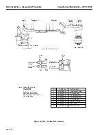
8. Jack the turbine case to exhaust frame flange (position 2) to 0.004
±
0.001 in. Record all dial indica-
tor readings. Recheck all jacks for snugness.
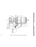
9. Jack the compressor discharge to turbine casing flange (position 3) to 0.002 –0.003 in. Record all
dial indicator readings. Recheck all jacks for snugness.
10. Jack the aft or compressor case to compressor discharge flange (position 4) to 0.002–0.003 in. Re-
cord all dial indicators. Recheck all jacks for snugness.
11. Jack the forward compressor case to aft compressor case flange (position 5 if applicable) to
0.002–0.003 in. Record all dial indicators. Recheck all jacks for snugness.
CAUTION
Do not, under any circumstances remove the mechanical
support jacks or dial indicators until all upper half casings
have been reinstalled and bolted up.
Note:
To prevent out-of-roundness occurring all casings should not be un-
bolted prior to removal. This is very tempting to do when running more
than one (1) shift operation with only one (1) shift crane coverage.
It is permissible to remove every other bolt on the horizontal joint and
every other bolt in the vertical joint except for the top six casings should
not be replaced without being bolted. Again, every other bolt on the
horizontal and vertical joint with six on top is permissible.
Casings should be removed in the following sequence; exhaust frame,
forward compressor case, inlet case, turbine case and compressor dis-
charge. Reinstallation is in the reverse order, i.e. compressor discharge
case, turbine case, etc.
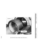
Operation 8 — How to Remove Upper Half Exhaust Frame
Note:
The rail beam, trolley hoist and spreader bar are applicable to vertical
exhaust stack configurations only. On side exhaust stack configura-
tions the cowl cover on the exhaust plenum is removed for access to the
exhaust frame for removal using an overhead crane and normal
rigging.
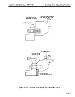
1. Install the rail beam, trolley hoist, and spreader bar used for exhaust frame and turbine casing re-
moval inside the exhaust duct transition piece.
2. Disconnect and remove as necessary all instrumentation tubing for wheelspace thermocouples and
pressures inside the inner barrel tunnel.
3. Remove the left and right side outer horizontal joint insulating packs and identify for location.
4. Remove the outer insulating pack on the upper half aft vertical flange.
5. Remove the upper half vertical bolting between turbine case and exhaust frame.
Содержание MS6001B
Страница 2: ...Gas Turbine Inspection and Maintenance GEK 107048 I 2 THIS PAGE INTENTIONALLY LEFT BLANK ...
Страница 4: ...Inspection and Maintenance Note THIS PAGE INTENTIONALLY LEFT BLANK ...
Страница 12: ...Inspection and Maintenance Notes Cautions and Warnings viii THIS PAGE INTENTIONALLY LEFT BLANK ...
Страница 13: ...INSERT TAB INTRODUCTION ...
Страница 14: ......
Страница 25: ...INSERT TAB STANDARD PRACTICES ...
Страница 26: ......
Страница 57: ...Standard Practices Inspection and Maintenance GEK 107048 SP 31 Figure 2 26 Rail Fabrication Hoist ...
Страница 58: ...Inspection and Maintenance GEK 107048 Standard Practices SP 32 Figure 2 27 Pulley Nozzle Segments ...
Страница 59: ...Standard Practices Inspection and Maintenance GEK 107048 SP 33 Figure 2 28 Typical Borescope Kit ...
Страница 60: ...Inspection and Maintenance GEK 107048 Standard Practices SP 34 Figure 2 29 Rail Channel Trolley ...
Страница 61: ...Standard Practices Inspection and Maintenance GEK 107048 SP 35 Figure 2 30 Lifting Beam Inlet Silencer ...
Страница 62: ...Inspection and Maintenance GEK 107048 Standard Practices SP 36 Figure 2 31 Lifting Beam Inlet Transition ...
Страница 63: ...Standard Practices Inspection and Maintenance GEK 107048 SP 37 Figure 2 32 Lifting Beam Inlet Elbow ...
Страница 66: ...Inspection and Maintenance GEK 107048 Standard Practices SP 40 Figure 2 38 Tubing Insert and Male Connector ...
Страница 86: ...Inspection and Maintenance GEK 107048 Standard Practices SP 60 THIS PAGE INTENTIONALLY LEFT BLANK ...
Страница 87: ...INSERT TAB AUXILIARY CONTROLS SYSTEMS MAINTENANCE ...
Страница 88: ......
Страница 90: ...Auxiliary and Controls Systems Maintenance Inspection and Maintenance THIS PAGE INTENTIONALLY LEFT BLANK ...
Страница 104: ...Auxiliary and Controls Systems Maintenance Inspection and Maintenance ACSM 14 THIS PAGE INTENTIONALLY LEFT BLANK ...
Страница 106: ...Inspection and Maintenance Procedures Inspection and Maintenance I 2 THIS PAGE INTENTIONALLY LEFT BLANK ...
Страница 132: ...Inspection and Maintenance Procedures Inspection and Maintenance IMP 26 THIS PAGE INTENTIONALLY LEFT BLANK ...
Страница 133: ...INSERT TAB SCHEDULED TURBINE MAINTENACE ...
Страница 134: ......
Страница 153: ...Scheduled Turbine Maintenance Inspection and Maintenance GEK 107048 STM 19 Figure 4 2 Borescope Light Supply ...
Страница 156: ...Inspection and Maintenance GEK 107048 Scheduled Turbine Maintenance STM 22 Figure 4 5 TV Monitor Presentation ...
Страница 157: ...INSERT TAB COMBUSTION INSPECTION ...
Страница 158: ......
Страница 160: ...Inspection and Maintenance GEK 107048 Combustion Inspection 2 THIS PAGE INTENTIONALLY LEFT BLANK ...
Страница 239: ...INSERT TAB HOT GAS PATH INSPECTION ...
Страница 240: ......
Страница 242: ...Inspection and Maintenance GEK 107048 Hot Gas Path Inspection 2 THIS PAGE INTENTIONALLY LEFT BLANK ...
Страница 313: ...INSERT TAB MAJOR INSPECTION ...
Страница 314: ......
Страница 316: ...Inspection and Maintenance GEK 107048 Major Inspection 2 THIS PAGE INTENTIONALLY LEFT BLANK ...
Страница 350: ...Inspection and Maintenance GEK 107048 Major Inspection Inspection Procedures MI I 8 THIS PAGE INTENTIONALLY LEFT BLANK ...
Страница 363: ...INSERT TAB MAINTENANCE FORMS ...
Страница 364: ......
Страница 370: ...Inspection and Maintenance GEK 107048 Maintenance Forms MF 6 THIS PAGE INTENTIONALLY LEFT BLANK ...

