PowerVault ML6000 Maintenance Guide
185
Removing the Cable Spool
1
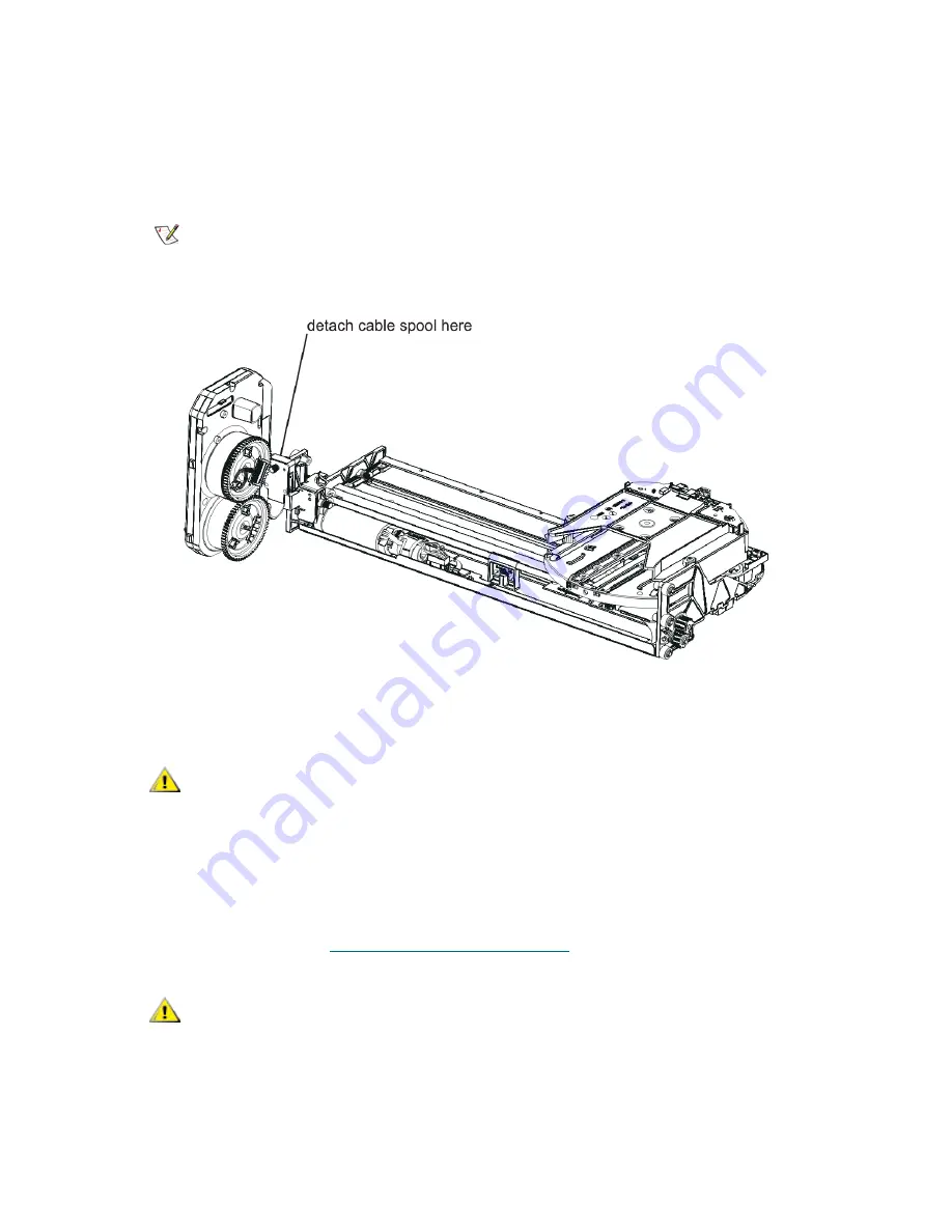
While holding the picker securely in your hand, reach inside the 5U Library Control Module and remove
the cable spool clip from the Y-carriage assembly. Unscrew the thumbscrew that attaches the cable
spool to the Y-carriage assembly, let the picker drop down, and pull the cable spool clip off of the
assembly.
2
Remove the entire robot assembly from the 5U Library Control Module.
To remove the robot assembly, lift the assembly up and out of the top of the 5U Library Control Module.
3
Remove the three tape columns located on the left side of the 5U Library Control Module.
You must remove the tape column located at the front left of the module before removing the other two
tape columns. Remove each column by pulling it forward (toward the front of the library) until it unsnaps
from the chassis wall, and then pull it gently to the center of the library. For more instructions on
removing the columns, see
Removing and Replacing Columns
on page 189.
Note
The figure below shows the Model 1 robot assembly and cable spool. If you
are working on a Model 2 robot assembly and cable spool, they will look
slightly different, but the way they attach together is the same.
CAUTION
Do not support the Y-carriage assembly by the thin metal rod. Lifting
the assembly by the thin metal rod will bend the rod.
CAUTION
Tape columns must be replaced in their original locations, because
each column has fiducial indices that help to guide the picker
assembly. Consider labeling the tape columns so you can be sure
that you replace them in their original locations. Otherwise, the
library’s self-test will fail.
Содержание PowerVault ML6000
Страница 1: ...w w w d e l l c o m s u p p o r t d e l l c o m MaintenanceGuide Dell PowerVault ML6000 ...
Страница 14: ...xiv Tables ...
Страница 18: ...xviii Figures ...
Страница 452: ...434 Troubleshooting the Tape Library ...
Страница 456: ...438 Library Drawings Library Rear View Figure 32 ML6020 Rear View ...
Страница 463: ...PowerVault ML6000 Maintenance Guide 445 Figure 42 Model 1 Picker Assembly Figure 43 Model 2 Picker Assembly ...
Страница 466: ...448 Library Drawings Figure 46 Model 1 Parking Tab Parked Figure 47 Model 2 Parking Tab Parked ...
Страница 467: ...PowerVault ML6000 Maintenance Guide 449 Library Control Blade LCB Figure 48 Library Control Blade ...
Страница 468: ...450 Library Drawings Power Supplies Figure 49 Power Supplies ...
Страница 475: ...PowerVault ML6000 Maintenance Guide 457 Rack mounted Library Figure 56 Rack mounted Library Front ...
Страница 477: ...PowerVault ML6000 Maintenance Guide 459 Figure 58 Electrical System 5U Library Control Module ...
Страница 478: ...460 Library Drawings Figure 59 LCB Functions ...
Страница 479: ...PowerVault ML6000 Maintenance Guide 461 ...
Страница 480: ...462 Library Drawings Figure 60 Accessor Control Block Figure 61 Door and Import Export Board DIEB ...
Страница 481: ...PowerVault ML6000 Maintenance Guide 463 Figure 62 Door and Display Block Figure 63 Power System Block ...
Страница 482: ...464 Library Drawings Figure 64 Fan Control Board ...
Страница 483: ...PowerVault ML6000 Maintenance Guide 465 Figure 65 Library Cables ...
Страница 484: ...466 Library Drawings Figure 66 Library System Grounding ...
Страница 485: ...PowerVault ML6000 Maintenance Guide 467 Figure 67 Library Power System ...
Страница 486: ...468 Library Drawings ...
Страница 494: ...476 Glossary Y axis Y position The vertical position of the library s robotic arm ...


