Chevrolet 1977 10 Series Скачать руководство пользователя страница 85

REAR  AXLE  DIFFERENTIAL

4B-13

the  pinion  depth  and  ring  gear-to-pinion  backlash.

Gear Tooth  Contact  Pattern  Check

Prior  to  final  assembly  of the  differential,  a  G ear Tooth 

Contact  P attern  Check  is  necessary  to  verify  the  correct 
relationship  between  ring  ear  and  drive  pinion.  G ear  sets 
which are not positioned properly may be noisy, or have short 
life, or both.  W ith a pattern check,  the most desirable contact 

between  ring  gear  and  drive  pinion  for  low  noise  level  and 

long  life  can  be  assured.

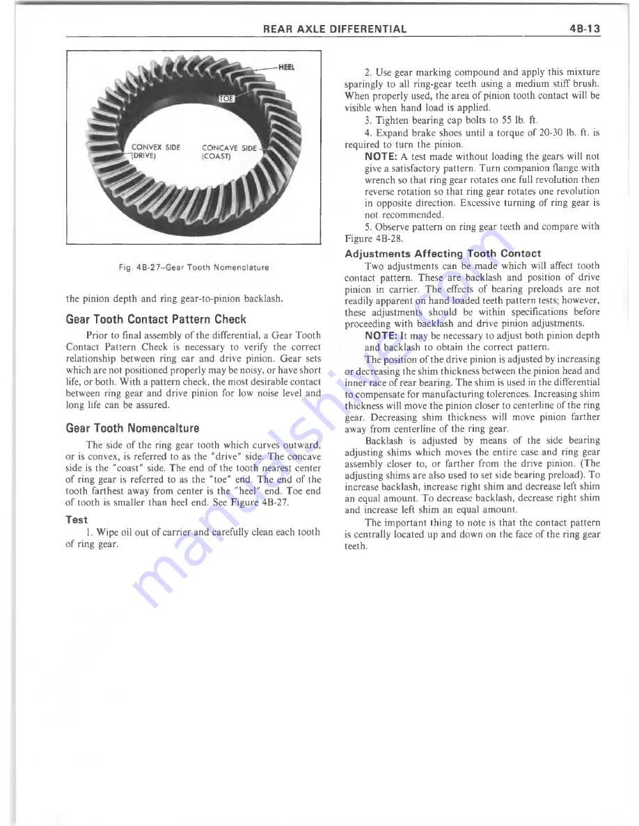
Gear Tooth  Nomencalture

The  side  of the  ring  gear  tooth  which  curves  outw ard, 

or  is  convex,  is  referred  to  as  the  "drive"  side.  The  concave 
side  is  the  "coast"  side.  The  end  of the  tooth  nearest  center 
of ring  gear  is  referred  to  as  the  "toe"  end.  The  end  of the 
tooth  farthest  away  from  center  is  the  "heel"  end.  Toe  end 
of tooth  is  sm aller  than  heel  end.  See  Figure  4B-27.

Test

1. 

Wipe  oil  out  of carrier and  carefully clean  each  tooth 

of ring  gear.

2.  Use  gear  m arking  com pound  and  apply  this  m ixture 

sparingly  to  all  ring-gear  teeth  using  a  medium  stiff  brush. 
W hen  properly  used,  the area of pinion  tooth  contact  will  be 
visible  when  hand  load  is  applied.

3.  Tighten  bearing  cap  bolts  to  55  lb.  ft.
4.  Expand  brake  shoes  until  a  torque  of 20-30  lb.  ft.  is 

required  to  turn  the  pinion.

NOTE: 

A  test  m ade  w ithout  loading  the  gears  will  not 

give a satisfactory  pattern.  Turn  companion  flange  with 
wrench  so that  ring  gear rotates one full  revolution  then 
reverse  rotation  so  that  ring  gear  rotates  one  revolution 
in  opposite  direction.  Excessive  turning  of  ring  gear  is 
not  recommended.

5.  Observe pattern  on  ring  gear teeth  and compare  with 

Figure  4B-28.

Adjustments  Affecting  Tooth  Contact

Two  adjustm ents  can  be  made  which  will  affect  tooth 

contact  pattern.  These  are  backlash  and  position  of  drive 
pinion  in  carrier.  The  effects  of  bearing  preloads  are  not 
readily apparent on hand loaded teeth pattern tests; however, 
these  adjustm ents  should  be  within  specifications  before 
proceeding  with  backlash  and  drive  pinion  adjustments. 

NOTE: 

It  may  be necessary to adjust both  pinion  depth 

and  backlash  to  obtain  the  correct  pattern.
The position of the drive pinion is adjusted by increasing 

or decreasing the shim thickness between the pinion head and 
inner race of rear bearing.  The shim is used in the differential 
to compensate for m anufacturing tolerences.  Increasing shim 
thickness  will move the pinion closer to centerline of the  ring 
gear.  Decreasing  shim  thickness  will  move  pinion  farther 
away  from  centerline  of the  ring  gear.

Backlash  is  adjusted  by  means  of  the  side  bearing 

adjusting  shims  which  moves  the  entire  case  and  ring  gear 
assembly  closer  to,  or  farther  from  the  drive  pinion.  (The 
adjusting shims are also used  to  set side bearing  preload).  To 
increase backlash,  increase  right  shim  and  decrease  left  shim 
an  equal  am ount.  To  decrease  backlash,  decrease  right  shim 
and  increase  left  shim  an  equal  am ount.

The  im portant  thing  to  note  is  that  the  contact  pattern 

is  centrally  located  up  and  down  on  the  face  of the  ring  gear 
teeth.

Содержание 1977 10 Series

Страница 1: ......

Страница 2: ......

Страница 3: ...imize the risk of personal injury to service personnel or the possibility that improper service methods will be followed which may damage the vehicle or render it unsafe It also is important to unders...

Страница 4: ......

Страница 5: ...the latest product inform ation available at the tim e of publica tion approval The right is reserved to make changes at any tim e w ithout notice CAUTION This vehicle contains some parts dimensioned...

Страница 6: ......

Страница 7: ...lace excessive tension on lines or hoses When a compressor is removed from the vehicle for servicing the amount of oil remaining in the compressor should be drained and measured This oil should then b...

Страница 8: ...Clutch Plate and Hub Assembly 1 I Retainer Ring 1 i i Lock Nut Suction Screen Drain Plug Oil Pump G e a r j Discharge Valve Plate Assembly Rear Suction Reed Axial Plate Bushing Needle Bearing O Ring...

Страница 9: ...nstall the retainer ring see installed Retainer Ring in inset of Fig 2 with convex side of ring facing spacer 6 Use Thin Wall Socket J 9399 and Clutch Hub Holder J 25030 or J 9403 to install a new sha...

Страница 10: ...of pulley clean If frictional surface of pulley shows any indication of damage due to overheating the pulley and bearing should be replaced 2 Check bearing for brinelling excessive looseness noise and...

Страница 11: ...g certain that it is properly seated in ring groove 3 Install pulley and bearing assembly as described in Compressor Pulley and Bearing Asm Replacement procedure 4 Install clutch plate and hub assembl...

Страница 12: ...ean paper orderliness in the work area and a place for all parts being removed and Fig 13 Removing Pulley and Bearing Retainer Ring replaced is of great importance as is the use of the proper clean se...

Страница 13: ...TO PURGE THE SYSTEM OF REFRIGERANT as outlined earlier in the Service Manual Remove 1 After first purging the system of refrigerant remove the clutch plate and hub assembly and shaft key as described...

Страница 14: ...pressor neck making certain it is installed in bottom groove Fig 20 and Fig 21 Top groove is for retainer ring Use O Ring Installer J 21508 2 Coat the O ring and seal face of the new seal assembly wit...

Страница 15: ...e result of mispositioning of the axial plate on the compressor shaft The mispositioning of the axial plate may be caused by improper procedures used during pulley and driven plate removal pounding co...

Страница 16: ...reed retainers to pry up on assembly Fig 26 Do not position screwdrivers between reeds and reed seats 10 Examine valve reeds and seats Replace entire assembly if any reeds or seats are damaged 11 Usin...

Страница 17: ...ssor Internal Mechanism Removal procedure 2 Identify by pencil mark or some other suitable means each piston numbering them as 1 2 and 3 Fig 30 Number the piston bores in the front cylinder half in li...

Страница 18: ...on original factory equipment as ends of the tube are swedged into cylinder halves The discharge cross over tube in internal mechanism assemblies that have been previously serviced have an O ring and...

Страница 19: ...tion piston over No 1 cylinder bore notched end of piston being on bottom and piston straddling axial plate and lower the shaft to allow piston to drop into its bore Fig 38 11 Repeat Steps 6 through 1...

Страница 20: ...TCHED COMBINATION OF SHOE DISC TO REAR BALL AND SPHERICAL CAVITY IN PISTON MUST BE KEPT IN PROPER RELATIONSHIP during disassembly after gaging operation and during final assembly of internal mechanism...

Страница 21: ...LLY slicing through the ring with a knife or sharp instrument holding the blade almost flat with the piston surface Be careful not to damage the aluminum piston OR piston groove in cutting to remove t...

Страница 22: ...ate the Piston and Ring Assembly in the Ring Sizer J 24608 6 several COMPLETE turns until the Assembly rotates relatively free in the Ring Sizer Fig 48 8 Remove the Piston and Ring Assembly wipe the e...

Страница 23: ...oe disc on the rear over the axial plate Hold front thrust bearing pack tightly against axial plate hub while lifting hub Insert the Piston Assembly into Fig 49 Gaging Piston Ring Size Fig 5 0 ln sta...

Страница 24: ...ns in front cylinder half if previously removed 4 Install front suction reed plate on front cylinder half Align with dowel pins suction ports oil return slot and discharge cross over tube Fig 57 5 Ins...

Страница 25: ...2 Install new dowel pins in rear cylinder half if previously removed 13 Install new O ring in oil pick up tube cavity 14 Lubricate oil pick up tube with 525 viscosity refrigerant oil and install into...

Страница 26: ...nism twist front head assembly back and forth very slightly by hand until rear head drops over dowel Fig 6 2 1nsta lling A 6 Compressor Shell pins 25 Install nuts on threaded shell studs and tighten e...

Страница 27: ...ONING 1B 21 Fig 6 5 A 6 Shell To Front Head O Ring Installation CAVITY BETW EEN GEAR TEETH 3 O C LO C K O IL SUMP 6 O C LO C K O IL DRA IN PLUG Fig 6 4 Positioning Oil Pump Gears F R O N T H E A D IN...

Страница 28: ...bolt driven metal flanges in the O Ring cavities could damage the seal surface of the compressor Some service operations can be performed without disturbing the internal mechanism completely removing...

Страница 29: ...Plate 27 Ring Seal 5 Rotor Bearing 19 O Ring 28 Main Bearing 6 Rotor and Bearing Assy 20 Retaining Ring 29 Front Head Assy 7 Retaining Ring 21 Valve Plate Assy 30 Screw and Washer Assy 8 Clutch Drive...

Страница 30: ...tch plate and hub assembly 3 Align shaft key with shaft keyway and assemble clutch plate and hub assembly on compressor shaft CAUTION To avoid internal damage to compressor do not drive or pound on cl...

Страница 31: ...seal spring pressure and turn tool clockwise to engage seal assembly tabs with tangs of tool Remove seal assembly by pulling straight out from compressor shaft Fig 74 Discard seal 6 Remove seal seat...

Страница 32: ...ch Plate and Hub Assembly 2 Remove rotor and bearing assembly retaining ring using snap ring pliers J 6083 Fig 76 Mark the location of clutch coil terminals If clutch rotor and or rotor bearing only a...

Страница 33: ...rim mounting screws as described in Step 2 2 Place rotor and bearing assembly on blocks Fig 81 and drive bearing out of rotor hub with rotor bearing remover and rotor assembly installer J 25029 It wil...

Страница 34: ...e J 8092 as shown in Fig 84 force will be applied to the inner race of the bearing when Fig 8 3 Installing Rotor and Bearing Assembly installing the assembly on the front head of the compressor 5 Inst...

Страница 35: ...Tighten pulley rim mounting screws to 100 inch pounds torque and lock screw heads in place FRONT HEAD AND MAIN BEARING ASSEMBLY Removal 1 Remove clutch rotor and bearing assembly but do not loosen or...

Страница 36: ...asher on shaft with the tang pointing down Fig 87 5 Lubricate the three washers with clean oil 525 Viscosity and assemble front head to cylinder MAIN BEARING REPLACEMENT Removal 1 Remove front head as...

Страница 37: ...ompressor shell remove holding fixture J 25008 1 from compressor reverse fixture to again hold compressor by the opposite side using the short length screws At this point the valve plate retainer ring...

Страница 38: ...with the A C controls set for Maximum Cooling and High Blower prior to discharging the system Add additional oil as indicated in Diagnosis Section of this Service Manual Oil Charge Compressor Replace...

Страница 39: ...ressure line or a HIGH pressure gage and Gage Adapter J 5420 to the Test Plate J 9625 HIGH side connector 13 Attach a Adapter J 5420 to the suction or LOW pressure port of the Test Plate J 9625 to ope...

Страница 40: ...0 Compressing Fixture 26 J 5139 O il Pickup Tube Remover J 25498 3 8 A dapter 16 J 9403 Clutch Hub Holding Tool 27 J 9432 N eed le Bearing Installer 6 J 6084 Leak Detector 17 J 9399 9 16 Thin W a ll S...

Страница 41: ...n s ta lle r 3 J 2 4 8 9 5 M a in B e a rin g In s ta lle r 4 J 2 4 8 9 6 M a in B e a rin g Rem over 5 J 2 5 0 3 1 2 Rotor a n d B e a rin g P u ller 6 J 2 5 0 3 1 1 Rotor a n d B e a rin g P u lle r...

Страница 42: ......

Страница 43: ...e the steering gear in a vise clamping onto one of the mounting tabs The wormshaft should be in a horizontal position 2 Rotate the wormshaft from stop to stop counting the total number of turns Then t...

Страница 44: ...y Typical the side cover Remove the lash adjuster screw from the side cover by turning the screw clockwise Slide the adjuster screw and shim out of the slot in the end of the pitman shaft 10 Pry out a...

Страница 45: ...Wormshaft Bearing Race Replacement ADJUSTER PLUG RACES 1 All Except Corvette Remove the wormshaft bearing race using Tool J 5822 and a Slide Hammer as shown in Figure 3B 9 Corvette Using a hammer and...

Страница 46: ...balls have been installed the circuit is complete e Fill the remaining ball circuit in the same manner as described for the first circuit in Steps c and d above 5 Corvette only figs 3B 12 and 3B 13 a...

Страница 47: ...by rotating the nut on the worm to see that it moves freely Do not rotate the nut to the end of the worm threads as this may damage the ball guides If there is any stickiness in the motion of the nut...

Страница 48: ...ved from the wormshaft 5 Position the lash adjuster with shim in the slotted end of the pitman shaft Check the end clearance which should not be greater than 002 fig 3B 16 If clearance is greater than...

Страница 49: ...disassembly 1 Remove pump pulley by using tool J 25034 as shown in Figure 3B 18 2 Place the pump in a vise and remove the union and O ring seal assembly CAUTION In clamping pump in vise be careful not...

Страница 50: ...t plate as a result of normal wear Do not confuse this with scoring 4 Make certain vanes were installed with rounded edge toward pump ring and see that they move freely in rotor slots 5 If the flow co...

Страница 51: ...fig 3B 24 6 Place pump housing in a vise and install shaft thrust plate and rotor assembly into housing aligning the holes in the thrust plate with the dowel pins as shown in Figure 3B 25 7 Install t...

Страница 52: ...n the housing 13 Install the flow control spring and flow control plunger Be sure the hex head screw goes into the bore first fig 3B 31 14 On Corvette install cage and a new filter Fig 3B 26 lnstallin...

Страница 53: ...G DOWEL PIN HOLE CROSS OVER HOLE Fig 3B 28 Correct Vane Assembly Fig 3B 3 1 Installing Flow Control Valve Fig 3B 29 lnstalling Pressure Plate Spring Fig 3B 30 lnstalling End Plate Retaining Ring Fig 3...

Страница 54: ...foreign material are encountered the remaining components o f the entire hydraulic system should be disassembled inspected thoroughly cleaned and flushed before servicing is completed Disassembly Fig...

Страница 55: ...pitman shaft with a soft hammer and remove the pitman shaft and side cover from the housing Remove the side cover O ring and discard 5 Remove the rack piston as follows a Insert Ball Retainer Tool J...

Страница 56: ...t Bearing 25 Locknut 41 10 Thrust Washer Small 26 Attaching Bolts and Washers 42 11 Spacer 27 Side Cover 43 12 Retainer 28 0 Ring 44 13 0 Ring 29 Pitman Shaft 45 14 Spool Valve 30 Screws and Lock Wash...

Страница 57: ...lean solvent and dry parts with 10 11 1 Retaining Ring 5 Adjuster Plug 8 Thrust Bearing 2 Dust Seal 6 O Ring 9 Thrust Washer Sm all 3 O il Seal 7 Thrust Washer 10 Spacer 4 N ee d le Bearing Large 11 R...

Страница 58: ...he retainer is sealed to prevent interference with the valve body The spacer must be free to rotate Fig 3B 42 lnstalling Bearing J 7079 2 Disassembly 1 Remove and discard the O ring in the shaft cap e...

Страница 59: ...icate the spool valve with Power Steering Fluid and check the fit of the spool valve in the valve body with the spool valve dampener O ring removed If the valve does not rotate freely without binding...

Страница 60: ...ched assembly 3 Inspect ball return guide halves making sure that the ends where the balls enter and leave the guides are not damaged 4 Inspect lower thrust bearing and washers for scores or excessive...

Страница 61: ...ring with Internal Pliers J 4245 and remove outer steel washer Pry out the outer seal Remove the inner steel washer then pry out the inner seal fig 3B 52 Discard seals CAUTION When prying out seals be...

Страница 62: ...install seals with Installer J 6219 Install the inner single lip seal first then a back up washer Drive seal in far enough to provide clearance for the outer seal back up washer and retaining ring Mak...

Страница 63: ...the shoulder in the housing c With Ball Retainer J 7539 in place in the rack piston POSITION W ORM PIN IN VALVE BODY NOTCH Fig 3 B 5 8 ln sta llin g Valve Body push the rack piston with teeth toward...

Страница 64: ...ft from one stop to the other Count the number of turns and locate the center of travel then check the combined seal drag and thrust bearing preload by rotating the torque wrench through the center of...

Страница 65: ...STEERING 3B 23 Fig 3B 65 M easure Back and Remark Housing Fig 3B 67 Tighten Lock Nut...

Страница 66: ...ng Rack Piston Fig 3 B 7 0 T o rq u in g Over Center Locknut Fig 3B 69 A djusting Over Center Preload CONTROL VALVE CORVETTE INDEX Overhaul Operations 3B 25 Disassembly 3B 25 Inspection 3B 25 R epairs...

Страница 67: ...Cap Removal OPERATIONS Hold the bolt from rotating while turning the nut off the bolt This will force the washer against the port boss face and will back out the bolt thus drawing the connector seat...

Страница 68: ...to move out Then turn the nut counter clockwise until the rod just begins to move in Now turn the nut clockwise to exactly one half the rotation needed to change the direction of the piston rod movem...

Страница 69: ...STEERING 3B 27 Fig 3B 77 Turning A d ju ste r Plug out of Sleeve Fig 3B 79 lnstalling C onnector Seat Fig 3B 78 Removing C onnector Seat Fig 3B 80 Replacing A d juster Plug and Shaft...

Страница 70: ...e M ounting Bolts 15 Annulus Spacer 25 Sleeve Bearing 6 Lock W asher 16 Gasket 26 Adapter Housing 7 Valve Housing 17 Valve Shaft W asher 27 Lubrication Fitting 8 Valve Adjustm ent Spring 18 0 Ring Sea...

Страница 71: ...ll stud opening 7 If the ball seat is to be replaced it must be pressed out using Tool J 8937 Assembly 1 Reassemble the piston rod seal components by reversing the disassembly procedure Apply power st...

Страница 72: ...Bearing Race Remover 16 J 8433 Pump Pulley Remover Cast Pulley 17 J 1614 Pitman Shaft Bushing Remover 18 J 7539 Ball Retainer 19 J 7624 Spanner Wrench 20 J 4245 No 23 Internal Pliers 21 J 22670 Pump...

Страница 73: ...tte and on truck models with 8 7 8 inch ring gears However if J 21777 01 is not used in determining pinion depth shim requirements the following tools and procedures are recommended Only the steps of...

Страница 74: ...rd the result 4 Combine the pinion code number with 45 which represents a nominal pinion From that number subtract the dial indicator reading The result is the required shim thickness For example if t...

Страница 75: ...lash to avoid changing gear tooth contact 1 Remove screw that retains differential pinion shaft and remove pinion shaft 2 Remove rear axle shaft 3 Roll out the differenital pinions and thrust washers...

Страница 76: ...J 22175 for the 8 3 4 ring gear or J 25299 for 7 1 2 ring gear as shown in figure 4B 4 4 Before bearing installation on opposite hub support differential case on proper adapter plug This allows differ...

Страница 77: ...r Add together the dimesnions of the Service Shim Service Spacer and Feeler Gauge Record the result for each side 6 Use the sample procedure in Figure 4B 8 for the 8 1 2 and 8 3 4 ring gear Figure 4B...

Страница 78: ...Gauge C Fig 4B 7 Determ ining Side Bearing Shim Requirem ents 7 1 2 side an equal amount DRIVE PINION Removal 1 Remove differential as previously outlined 2 Check torque required to rotate drive pini...

Страница 79: ...auge C 265 010 240 TO M AIN TAIN PROPER BACKLASH 005 008 ring gear is moved away from pinion by subtracting 010 shims from ring gear side and adding 010 shims to other side 010 275 004 TO OBTAIN PROPE...

Страница 80: ...ng Ring Gear Backlash Bearing Removal and Cup Replacement 1 If front pinion bearing is to be replaced drive outer race from carrier using drift in slots provided for this purpose Tap alternately on op...

Страница 81: ...machine This setting may vary slightly Fig 4 B 15 Removing Drive Pinion from the design or nominal setting due to allowable variation in machining the parts When a pinion is found having a plus or min...

Страница 82: ...r tight to prevent the discs from moving 8 Position dial indicator J 8001 on the mounting post Fig 4B 19 Gauge Plate Installed of the arbor with the contact button resting on the top surface of the pl...

Страница 83: ...im selected in step 14 on the pinion shaft against pinion head 17 Lubricate the rear pinion bearing with liberal amounts of hypoid lubricant and install rear bearing onto pinion using J 8609 01 8 1 2...

Страница 84: ...tle at a time and torque should be checked after each slight Fig 4B 25 Drive Pinion Flange Installation amount of tightening Exceeding torque specifications may compress the collapsible spacer too far...

Страница 85: ...full revolution then reverse rotation so that ring gear rotates one revolution in opposite direction Excessive turning of ring gear is not recommended 5 Observe pattern on ring gear teeth and compare...

Страница 86: ...4B 14 OVERHAUL MANUAL Fig 4B 28 Gear Teeth C ontact Pattern Check...

Страница 87: ...Gear Repl 4B 16 Installation and Adjustments 4B 23 Gear Tooth Contact Pattern Installation and Adjustment 4B 17 4B 25 1 Companion Flange 2 Deflector 3 Pinion Oil Seal 4 Pinion Front Bearing 5 Pinion B...

Страница 88: ...6 Place left and right bearing cups with bearing caps so that they may be reinstalled in original positions Place shims with appropriate cups Inspection 1 Clean all parts in cleaning solvent inspect...

Страница 89: ...talled 5 Differential may be installed in carrier now or after service is perform ed on the drive pinion Installation and Adjustment 1 Check condition of bearing bearing cups cup seat in carrier and c...

Страница 90: ...uge C 265 010 240 TO M A IN TAIN PROPER BACKLASH 005 008 ring gear is moved away from pinion by subtracting 010 shims from ring gear side and adding 010 shims to other side 010 275 004 TO OBTAIN PROPE...

Страница 91: ...s are properly preloaded If any adjustments are required in later procedures make sure the preload rem ains as established in step 9 If backlash is changed in later steps be sure the total thickness o...

Страница 92: ...to locked position Remove flange by turning J 8614 3 while holding J 8614 11 as shown in figure 13B 6 To remove the drive pinion first thread the original pinion nut half way on the pinion for thread...

Страница 93: ...sing Installer J 0270 14 for Truck models and J 9745 for Passenger Car as shown in figure 16B Fig 15B Removing Drive Pinion Rear Bearing Fig 16B Installing Pinion Rear Bearing Cup 7 Install the front...

Страница 94: ...unted on preload stud J 21777 43 c For all models insert stud through rear bearing and pilot J 21777 35 and through front bearing and pilot J 21777 42 Install the hex nut until snug and rotate the bea...

Страница 95: ...t that many thousandths from the indicator reading For example if the indicator reading is 031 and pinion is marked 3 the correct depth shim for installation will be 031 003 028 inch 15 Remove bearing...

Страница 96: ...table thick washer or sheet metal plate over the pinion stem Install the original Fig 26B Installing Pinion Oil Seal Truck pinion nut and tighten sufficiently to draw pinion through the front bearing...

Страница 97: ...ion depth and the ring gear to pinion backlash Gear Tooth Contact Pattern Check Prior to final assembly of the differential a G ear Tooth Fig 28B Measuring Rotating Torque Contact Pattern Check is nec...

Страница 98: ...n head and inner race of rear bearing The shim is used in the differential to compensate for m anufacturing tolerances Increasing shim thickness will move the pinion closer to centerline of the ring g...

Страница 99: ...Pinion 19 Side Bearing Cap 26 Side Gear Yoke 2 Carrier Cover Pin Retainer Bolt Bearing Seal 3 Filler Plug 12 Hypoid Ring Gear 20 Side Bearing Cap 27 Side Gear Yoke 4 Cover Gasket 13 Hypoid Drive Pinio...

Страница 100: ...for spline wear or yoke cracking If equipm ent is available use magnetic penetrant method to check for minute fractures in yokes or gears Differential Bearing Replacement 1 Place Puller J 22888 over d...

Страница 101: ...d carrier caps to make sure they are free from nicks burrs and foreign m aterial 2 Lubricate bearings with axle lubricant Position cups on proper bearings then install differential assembly in carrier...

Страница 102: ...t Steps 5 6 and 7 9 The required thickness of the service shim is determined by subtracting the thickness of the service spacer from the higher of the two averaged readings obtained in Steps 7 and 8 E...

Страница 103: ...ndicular to tooth angle and in line with gear rotation 18 If variation in backlash exceeds 003 measure ring gear and case runout as shown in Figure 13C G ear runout should not exceed 003 should runout...

Страница 104: ...ting or scoring Discard all parts that show excessive wear or failure Pinion and or Bearing Replacement 1 If necessary to replace pinion bearings tap old cups out of carrier using a brass drift See Fi...

Страница 105: ...accuracy of measurements 2 Lubricate the front and rear pinion bearings which will be used in final assembly and position them in their respective races in the carrier 3 W ith cloverleaf gauge plate...

Страница 106: ...that m any thousandths to the indicator reading For example if indicator reading is 019 and pinion is marked 2 the correct depth shim for installation will be 019 002 021 inch b If the pinion has no...

Страница 107: ...ions in step 14 of Differential Case Installation and A djustm ent Following service to the Differential Case or to the Drive Pinion and Ring G ear a G ear Tooth Contact Pattern Check must be made to...

Страница 108: ...ash and drive pinion adjustments NOTE It may be necessary to adjust both pinion depth and backlash to obtain the correct pattern The position of the drive pinion is adjusted by increasing or decreasin...

Страница 109: ...ription 4B 38 Eaton P o sitractio n 4B 39 D isassem b ly 4B 39 In sp e c tio n 4B 40 R eassem bly 4B 40 Chevrolet Positraction 4B 42 D isassem b ly 4B 42 In sp e c tio n 4B 42 R eassem bly 4B 42 Power...

Страница 110: ...hevrolet use an optional Eaton Positive Locking differential that is serviced as an assembly only Truck 10 1 2 ring gear axles produced by D ana use only the optional Dana Power Lok shown in figure 17...

Страница 111: ...ng retainer from the case until enough of the retainer is exposed to perm it installation of bar stock and C clamp as shown in Figure 6D Center the bar stock over the axle shaft hole in the spring ret...

Страница 112: ...f overheating NOTE Clutch plates and discs are not serviced separately If replacem ent is re quired clutch pack must be replaced as an assembly 2 Inspect preload springs for distortion and other defec...

Страница 113: ...inion gears can be perform ed by reversing the pinion gear removal procedure Fig 12D Spring Pack Compressed for Installation 15 For all except Corvette assemble springs in spring retainer and clamp as...

Страница 114: ...pring from the case 3 Support an axle shaft in a vise and slide the case into the shaft then turn the case to remove both pinions and thrust washers NOTE The pinion shaft may be partially installed to...

Страница 115: ...d side gears into case 12 Mount the case onto the axle shaft locked in a vise Place both pinions and thrust w ashers into position 180 apart and carefully roll in by turning the case on the shaft NOTE...

Страница 116: ...tes and dished Belleville friction plates on each side of differential side gears transm its drive from differential case to axle shafts Carefully observe the order in which the plates are used since...

Страница 117: ...ial case over previously assembled parts with scribe markings on both halves of case in alignment 7 Install differential case bolts but do not tighten at this time 8 Before tightening bolts use axle s...

Страница 118: ...4B 51 Installation and Adjustment 4B 48 Installation and Adjustment 4B 51 1 Companion Flange 2 Oil Deflector 3 Oil Seal 4 Bearing Retainer 5 Shim 6 Pinion Front Bearing 7 Collapsible Spacer 8 Pinion...

Страница 119: ...rential from carrier Side Bearing Replacement 1 Install bearing puller J 8107 onto one side bearing with puller screw centered on pilot plug as shown in figure 4E Be sure to install puller fingers int...

Страница 120: ...t side nut using J 24429 as shown in figure 3E until the ring gear contacts the drive pinion Do not force the gears into contact so as to bind them At this point zero lash is obtained 3 Back off the l...

Страница 121: ...use a new one upon reassembly 4 Thread end of J 8614 3 into small O D end of J 8614 2 Then with J 8614 11 installed as in step 2 insert J 8614 2 into J 8614 11 and turn it 1 8 of a turn to locked posi...

Страница 122: ...using J 24433 3 Install the front and rear pinion bearing cups into the bearing retainer using driver handle J 8092 on J 8608 for the front cup and on J 24432 for the rear cup 4 Install the pinion st...

Страница 123: ...01 ADD 001 ADD 002 ADD 003 ON SERVICE PINION 0 SUBT 002 SUBT 001 ADD 001 ADD 002 1 SUBT 003 SUBT 002 SUBT 001 ADD 001 2 SUBT 004 SUBT 003 SUBT 002 SUBT 001 Fig 16E Pinion Depth Codes the shim dim ensi...

Страница 124: ...s 4 Apply load to gears by expanding brake shoes or by wrapping a heavy rag around the com panion flange to resist rotation NOTE A test made w ithout loading the gears will not give a satisfactory pat...

Страница 125: ...REAR AXLE DIFFERENTIAL 4B 53 Fig 18E Gear Teeth Contact Pattern Check...

Страница 126: ...2 The drive pinion assembly incorporates an inner and outer bearing shim pack The inner shim is used to maintain proper pinion depth The outer shim is used to maintain proper preload on the pinion be...

Страница 127: ...o remove the differential case fom the carrier Record the dimensions and location of the side bearing shims Remove the spreader tool Disassembly 1 Remove differential side bearings by placing J 22912...

Страница 128: ...he inner bearing cup Tag shims for reassembly 9 Remove rear pinion bearing using J 22912 and an arbor press Fig 5F Removing Pinion Nut Fig 6F Removing Companion Flange Inspection 1 Clean all gears and...

Страница 129: ...aring Fig 8F Screwdrivers Against Case Pinion Shims Ring gears and pinions are supplied in matched sets only M atching num bers on both pinion and ring gear are etched for verification If a new gear s...

Страница 130: ...or Pinion Code Chart remove an equal amount as was added or removed from the inner shim pack 5 Install outer cup in carrier bore using installer J 7818 with Drive Handle J 8092 6 Press rear pinion bea...

Страница 131: ...e shim just installed on the ring gear side of the case was 172 inch the correct shim dimension would be 329 172 157 006 163 inch 11 Spread the differential carrier as shown in figure 2F 12 Assemble t...

Страница 132: ...vel and long life can be assured Gear Tooth Nomenclature The side of the ring gear tooth which curves outward or is convex is referred to as the drive side The concave side is the coast side The end o...

Страница 133: ...to obtain the correct pattern The position of the drive pinion is adjusted by increasing or decreasing the shim thickness of the inner shim located between the rear bearing cup and the carrier housin...

Страница 134: ...f shaft attached to wheel hub by studs and nuts W heel is supported by tapered roller bearings at outer end of axle housing a Remove axle shaft to hub attaching nuts b Rap on axle shaft to loosen shaf...

Страница 135: ...7F and remove flange from drive pinion Remove drive pinion from carrier 4 W ith a long drift tap on inner race of outer pinion bearing to remove pinion oil seal slinger gasket outer pinion cone and ro...

Страница 136: ...ing gear removed from the case Again install differential case and check runout at differential case flange 8 Should runout of case flange be greater than 002 the defect is probably due to bearings or...

Страница 137: ...om original build up If a new gear set is being used notice the plus or minus etching on both the old and new pinion and adjust the thickness of the old shim pack to compensate for the difference of t...

Страница 138: ...esh W ith force still applied set indicator to O 4 Reposition screw drivers on opposite side of ring gear and pry ring gear as far as it will go Now take an indicator reading Repeat until the same rea...

Страница 139: ...ad method as described earlier in D ana 10 1 2 Ring G ear section under G ear Tooth Contact Pattern Check Refer to figure 25F 8 Using a new gasket install housing cover and torque bolts to specificati...

Страница 140: ...m bly 4B 71 Ring G ear and Pinion A djustm ent 4B 71 Backlash and Preload A djustm ent 4B 71 Ring G ear T hrust Pad A justm ent 4B 72 In stallatio n 4B 72 1 Universal Joint Yoke 2 Pinion Bearing Oil S...

Страница 141: ...tial bearing outer races are not dropped while removing assemblyfrom carrier 6 Remove the bolts which attach the pinion bearing retainer to the carrier 7 Remove the pinion and bearing assembly from th...

Страница 142: ...washer and nut Torque nut to specifications and install cotter pin without backing off on nut Differential Disassembly 1 Check differential case to make sure that the two halves are marked so they ma...

Страница 143: ...two guide pins and install rem aining two bolts Torque all bolts alternately and evenly to specifications Reassembly 1 Place new pinion bearing retainer gasket on the retainer and install pinion assem...

Страница 144: ...during locking process This adjustm ent provides 005 in to 007 in clearance between thrust pad and ring gear face Installation 1 Clean out axle housing and cover and place new gasket over axle housing...

Страница 145: ...accomplished through the use of a flyweight governor mechanism cam system and multi disc clutch The flywheights on the governor mechanism move outward to engage a latching bracket whenever the wheel t...

Страница 146: ...ual transmission slowly engage clutch 8 Locked rear wheel will remain stationary and free wheel will begin turning It is important that brakes or clutch be released slowly enough to start the free whe...

Страница 147: ...ig h t spring B Replace governor assembly and latching bracket C F lyw eight in governor assembly stuck open C Replace governor assembly and latching bracket D Broken cam plate and or governor drive...

Страница 148: ...excessive wear and breakage Replace parts as needed The following are serviceable components for this differential Governor assembly and latching bracket with spring and stop pin Cam plate Clutch disc...

Страница 149: ...one pinion gear through the small window opening in the case while at the same time inserting the reaction block and other pinion gear through the large window opening Rotate the two pinion gears and...

Страница 150: ...es must be carefully measured for thickness and replaced with a piece of the same size CAM CLUTCH SERVICE Disassembly If cam plate or clutch discs must be replaced the cam gear sub assembly must be se...

Страница 151: ...lock is used determine face to face thickness of original blcok with calipers and replace with a service block of the same thickness NOTE INCORRECT BLOCK THICKNESS WILL DISTURB CRITICAL CLEARANCES AND...

Страница 152: ...case so holdes in housing will line up for the governor assembly and ltaching bracket shafts 13 Turn entire unit over and install three 3 seres 14 Lock an axle shaft in a vise in a vertical position...

Страница 153: ...50 Ft Lbs Torque Wrench J 21777 42 Front Bearing Plug 16 J 5853 In Lbs Torque Wrench J 21777 43 Stud 17 J 7137 Pinion Front Bearing Cup Installer 3 J 22779 Side Bearing Shim Gauge Used with J 8092 J 2...

Страница 154: ...ng Adapter 23 Drive Pinion F ront Bearing Cup Installer 24 Used w ith J 8092 Drive Pinion Rear Bearing Cup Installer Used w ith J 8092 J 22175 D ifferential Bearing Installer J 22888 D ifferential Bea...

Страница 155: ...taller 6 J 1364 Pinion Bearing Ring Drive 18 J 24385 Case Spreader Tool 7 J 1488 D ifferential Side Bearing Replacer 19 J 24430 Side Bearing Installer 8 J 8608 Drive Pinion Rear Bearing Cup Installer...

Страница 156: ......

Страница 157: ...or at one end of opening in carrier to indicate width of opening 5 Expand spreader tool to spread carrier a maximum of 020 CAUTION Do not attemtp to remove differential without using the spreader tool...

Страница 158: ...rential Bearing Cap 32 Differential Carrier 5 Drive Pinion Shims 23 Differential Bearing Cone 33 Inner Bearing Cone 6 Inner Bearing Shims 15 Differential Pinion 24 Differential Bearing Cup 34 Inner Be...

Страница 159: ...Pinion Shaft 5 Gasket 13 Cone and Roller 20 Shims Differential 27 Thrust Washer 6 Outer Pinion Oil Slinqer Inner Pinion Adjusting Pinion 7 and 8 Cone and Roller 14 Ring and Pinion 21 Cone and Roller 2...

Страница 160: ...a frosted condition with occasional slight scratches on races or rollers This does Fig 4C 6 Removing Inner Pinion Bearing Cone and Roller not indicate a defective bearing 2 Inspect pinion splines and...

Страница 161: ...oad Ring gears and pinions are supplied in matched sets only Matching numbers on both pinion and ring gear are etched for verification If a new gear set is being used verify the numbers of each pinion...

Страница 162: ...n the differential case and differential bearing on the ring gear side Remove differential bearing from the ring gear side and assemble proper amount of shims Reassemble bearing 5 Remove the different...

Страница 163: ...on then reverse rotation so that ring gear rotates one revolution in opposite direction Excessive turning of ring gear is not recommeded 5 Observe pattern on ring gear teeth and compare with Figure 4C...

Страница 164: ...4C 8 OVERHAUL MANUAL Fig 4C 12 Gear Tooth Pattern Contact Pattern...

Страница 165: ...ne 5 J 6368 Installer Pinion outer bearing cup use w ith J 8092 6 J 8092 Driver Handle use with J 6368 7 J 9276 2 Installer Pinion inner bearing 11 J 8001 12 J 22912 13 J 23494 Holder and Remover Comp...

Страница 166: ......

Страница 167: ...velle Place Tool J 22893 inside tilted mounting bracket Place Spanner Wrench J 9504 on top of J 22893 and tighten nuts and washers securing spanner wrench d Press down on Spanner Wrench J 9504 and rot...

Страница 168: ...ary support plate 7 Remove the reaction piston and reaction disc from the center of the secondary power piston by pushing down on the end of the reaction piston with a small object such as a pencil wo...

Страница 169: ...ther method requires the use of snap ring pliers Approximately 5 8 from the pointed ends of the pliers file or saw a small slot approximately 1 32 1 16 wide and 1 10 deep on each half of the pliers Ro...

Страница 170: ...to doubt cleanliness such as parts dropped or left exposed for eight hours or longer CAUTION I f there is any suspicion of Fig 5 8A P ositioning Prim ary Power Piston in Tool J 23101 Small Dia End Up...

Страница 171: ...of floating control valve Retainer Installer J 23175 fig 5 11A Place over the push rod so that the closed side of the retainer seats on the floating control valve With Installer J 23175 manually press...

Страница 172: ...ont and rear housings 27 Hold the housing divider so that the formed over flange that holds the primary diaphragm of the divider faces down Place the secondary bearing in the I D of the divider so tha...

Страница 173: ...rench and twist rear housing clockwise in relation to front housing until fully locked NOTE If unit is not easily locked hold housings together and apply vacuum to check valve in front housing Do not...

Страница 174: ...te bending or damage to studs 12 Place power unit with Holding Fixture J 22805 in an arbor press with rear housing up and secure to plate of press by a suitable means of holding Tool J 22805 fig 5 4B...

Страница 175: ...g Tool J 22677 fig 5 8B The flat rubber surface of the seal should be 5 16 below the flat inside surface of the rear housing 2 Install reaction disc in hub of front plate with small tip toward hole Us...

Страница 176: ...lace a piece of flat stock steel over end of pipe 14 Install diaphragm return spring so that small end of spring is against front housing 15 Place rear housing over front housing and align scribe mark...

Страница 177: ...master cylinder piston rod flat end first into the piston rod retainer Fig 5 7B Rear Bearing and Rear Shell Fig 5 8B Installing Rear Bearing and Vacuum Seal 4 Press down on the master cylinder piston...

Страница 178: ...t to eliminate bending or damage to studs Clamp base in bench vise with power section up fig 5 2C 3 Separate front and rear housings as follows a Straight Mounting Bracket Fig 5 3C Place Spanner Wrenc...

Страница 179: ...n place on push rod remove silencer 6 Remove seal and vacuum check valve and grommet from front housing Power Piston Assembly Group Fig 5 5C CAUTION Care must be used in handling the diaphragm o f pow...

Страница 180: ...ig 5 7C Fig 5 6C Removing Lock Ring From Power Piston LOCK RING PUSH ROD R EACTION R E T A IN E R R E A C T IO N LEVERS 7 R E A C T IO N B UM PER 7 LOCK RING O 1 RING S N A P RING R E A C T IO N PLATE...

Страница 181: ...ate Remover 8 Remove diaphragm from support plate and lay both parts aside 9 Position power piston tube down in a tool fabricated from a piece of wood 2 x 4 x 8 long with a 1 3 8 hole in center clampe...

Страница 182: ...s are in equal to new condition Badly damaged items or those which would take extensive work or time to repair should be replaced In case of doubt install new parts for safety 2 Inspect in accordance...

Страница 183: ...valve face 1 Replace Air Valve Push Rod Assembly 1 Air valve scratches dents distortion or corrosion of I D or O D All seats to be smooth and free of nicks and dents 1 Do not repair Replace 2 Push ro...

Страница 184: ...ing retainer on snap ring Assemble reaction bumper into groove in end of air valve 20 Position air valve return spring large end down on spring retainer 21 The three reaction levers are now placed int...

Страница 185: ...boot will locate in holes in center of brackets 10 Using a 1 8 diameter rod or similar tool stake the front and rear housing in two places 180 apart figs 5 14C and 5 15C CAUTION The interlock tabs sh...

Страница 186: ...ate bending or damaging of studs fig 5 2A 9 Press down on Spanner Wrench J 9504 and rotate the rear housing clockwise to separate the two housings If the 1 Master Cylinder 2 Vacuum Check Valve 3 Gromm...

Страница 187: ...ck will fall from its location in the diaphragm plate hub Remove the air valve push rod assembly from the diaphragm plate Remove the reaction disc from its location in the diaphragm plate bore insert...

Страница 188: ...e lock Make sure the lock indexes and retains the air valve c Install the rolling diaphragm in the groove of diaphragm plate d Apply silicone lubricant to surface of reaction disc and position disc in...

Страница 189: ...vise bracket end up and use a hammer and chisel to cut the bracket nut that secures the Fig 5 1E Bendix Hydro Boost Brake Booster mounting bracket to the power section cut the nut at the open slot in...

Страница 190: ...in the bottom of the accumulator valve bore and remove the check valve from the bottom of the bore Discard the check valve and O ring NOTE Using a screw extractor damages the seat in the check valve...

Страница 191: ...ool over the input rod end and down to the second groove then slide the forward seal off the tool and into the groove Assemble the other seal in the first groove Be sure that both seals are fully seat...

Страница 192: ...hammer and a small punch inserted into the staking groove of the nut at the slot in the booster hub fig 5 7E to stake the nut in place Be sure that the outer thread of the nut is upset Fig 5 7E S tak...

Страница 193: ...75 Control Valve Installer 5 J 21601 Power Brake Retainer and Installer 15 J 23188 Secondary Bearing Protector 6 J 22657 Bushing Retainer Socket 16 J 24551 Piston Installer 7 J 22647 Height Gauge 17 J...

Страница 194: ......

Страница 195: ...1 and 2 Air Horn Removal 1 Remove choke vacuum break diaphragm hose 2 Remove vacuum break diaphragm assembly from air horn by removing two attaching screws These screws have a tapered head and do not...

Страница 196: ...Fig 6C 6 2 Remove float assembly from float bowl by lifting upward on float hinge pin Remove hinge pin from float arm 3 Remove float needle from seat 4 Disconnect accelerator pump and power piston act...

Страница 197: ...e and pump discharge spring using needle nose pliers Fig 6C 10 12 Pump discharge ball and idle tube can be removed Fig 6C 7 Pump and Power Piston A ctuator Lever at the same time by inverting the bowl...

Страница 198: ...rottle body is necessary unless the idle mixture needle is damaged or the idle channels need cleaning If necessary to remove the idle mixture needle cut the tang from the plastic limiter cap Do not in...

Страница 199: ...uel bowl Tighten securely 4 Using wide blade screwdriver install needle seat and gasket 5 Install idle tube flush with bowl casting 6 Install pump ball spring and T into pump discharge hole Fig 6C 10...

Страница 200: ...t between both surfaces as shown 6 To adjust carefully bend metering rod holder up or down 7 Install air horn gasket on float bowl by carefully sliding slit portion of gasket over metering rod holder...

Страница 201: ...emaining adjustments MODEL 2GC 2GV CARBURETOR DISASSEMBLY Place carburetor on a holding fixture to prevent damage to throttle plates Figs 6C 18 and 19 Solenoid Assembly If Used CAUTION The electricall...

Страница 202: ...d from needle seat or from float assembly if pull clip is used 9 Remove float needle seat and gasket with a wide blade Fig 6C 22 Removing Vacuum Break Lever screwdriver 10 Remove power piston by depre...

Страница 203: ...alve and gasket from inside float bowl 3 Remove three screws holding venturi cluster to float bowl and remove cluster and gasket Then remove the plastic main well inserts in the main well cavity Fig 6...

Страница 204: ...nstalled no plastic limiter caps are required If the original idle mixture needles had to be removed install the idle mixture needle and springs into throttle body as described under Assembly No furth...

Страница 205: ...installed 4 Install inner choke coil lever and shaft assembly into choke housing 5 With the choke coil lever and shaft assembly installed into housing install the intermediate choke lever on flats of...

Страница 206: ...that the accelerator pump plunger is correctly positioned into pump well and will move freely 2 Install lockwashers and tighten eight air horn attaching screws evenly and securely according to sequen...

Страница 207: ...horn from float bowl by lifting straight up The air horn gasket should remain on the float bowl for removal later Fig 6C 40 CAUTION When removing air horn from float bowl use care to prevent bending t...

Страница 208: ...ve plastic filler block over float valve 7 Remove float assembly and float needle by pulling up on retaining pin Remove float needle seat and gasket Fig 6C 45 Fig 6C 38 R em oving Pump Lever 8 Remove...

Страница 209: ...y from choke housing Remove choke cover gasket if used On M4MC hot air choke model it is not necessary to remove baffle plate from beneath the thermostatic coil Distortion of the thermostatic coil may...

Страница 210: ...g 6C 49 Then remove thermostatic coil lever from flats on intermediate choke shaft Fig 6C 46 Removing A neroid Cavity Insert Remove intermediate choke shaft from the choke housing by sliding outward T...

Страница 211: ...cessary to remove the idle mixture needle destroy plastic limiter cap Do not install a replacement cap as a bare mixture screw is sufficient to indicate that the mixture has been re adjusted CLEANING...

Страница 212: ...eedles and springs until seated Back out the mixture needles 4 turns as a preliminary idle adjustment Final adjustment must be made on the engine using the procedures described under slow idle adjustm...

Страница 213: ...l Clip Location 7 Install aneroid cavity insert into float bowl 8 Install new needle seat assembly with gasket 9 To make adjustment easier bend float arm upward at notch in arm before assembly Install...

Страница 214: ...ot force the air horn assembly onto the bowl but rather lightly lower in place 2 Install two long air horn screws five short screws and two coutersunk screws into primary venturi area Install secondar...

Страница 215: ...before installing the choke thermostatic coil and cover assembly and gasket Refer to the Adjustment Procedures in Service Section 7 After the vacuum break fast idle cam choke rod and inside thermosta...

Страница 216: ...embled from the hanger by rotating ends out of the holes in the end of the hanger Fig 6C 61 5 Using special tool J 25322 drive small roll pin pump lever pivot pin inward just enough until pump lever c...

Страница 217: ...ig 6C 65 The power piston can be easily removed by pressing the piston down and releasing it with a snap This will cause the power piston spring to snap the piston up against the retainer This procedu...

Страница 218: ...metering jets if necessary NOTE No attempt should be made to remove the A P T metering screws or secondary metering orifice plates These items are fixed and if damaged float bowl replacement is requi...

Страница 219: ...4 Install fuel inlet filter spring filter new gasket and inlet nut and tighten nut securely 18 ft lbs CAUTION Tightening beyond specified torque can damage nylon gasket 5 If vacuum break diaphragm was...

Страница 220: ...osition gasket over two dowels on secondary side of bowl 21 Install pump plunger in pump well to complete float bowl assembly Air Horn 1 Install the following if removed choke shaft choke valve and tw...

Страница 221: ...in lower choke lever and retain in upper lever with horseshoe clip 6 Connect upper end of pump rod to pump lever by placing rod in specified hole in lever Align hole in pump lever with hole in air ho...

Страница 222: ...C 28 OVERHAUL MANUAL SPECIAL TOOLS J9789 02 UNIVERSAL CARBURETOR GAUGE SET J 9789 118 CARBURETOR HOLDING STAND J23417 CHOKE LEVER INSTALLING TOOL J26701 CHOKE VALVE ANGLE GAUGE Fig 6C 72 Special Tools...

Страница 223: ...from drive housing 4 Remove overrunning clutch from armature shaft as follows a Slide two piece thrust collar off end of armature shaft b Slide a standard half inch pipe coupling or other metal cylind...

Страница 224: ...eld frame a Release V spring from slot in brush holder support b Remove support pin c Lift brush holders brushes and spring upward as a unit d Disconnect leads from each brush e Repeat operation for o...

Страница 225: ...th a resulting decrease in cranking motor performance Fig 6D 4S Arm ature Short C ircuit Test CAUTION Some starter motor models use a molded armature commutator design and no attempt to undercut the i...

Страница 226: ...duces the bonding o f the molding material which holds the com mutator bars and since the molding materialis softer than the copper bars it is not necessary to undercut the material between the bars o...

Страница 227: ...assembly into place in drive housing engaging shift lever with clutch 4 Position field frame over armature and apply special sealing compound between frame and solenoid case Position frame against dr...

Страница 228: ...y pass terminal and contactor 4 Remove motor connector strap terminal and solder new terminal in position 5 Using a new battery terminal install terminal washer and retaining nut to end cover Install...

Страница 229: ...frame fig 6D 7C NOTE Diode trio may be checked for a grounded brush lead clip at this point Refer to diode trio checks 6 Remove the rectifier bridge attaching screw and the GENERATOR BAT terminal scre...

Страница 230: ...weakening If brushes appear satisfactory and move freely in brush holder springs may be reused TESTING Where specified conduct the following tests using an ohmmeter with a 1 1 2 volt cell and use the...

Страница 231: ...sleeve over the screw or damaged insulating sleeve Remove the screw to inspect the sleeve If sleeve or screw are not grounded replace regulator CAUTION Do not use high voltage such as 110 volt test l...

Страница 232: ...causing brush noise Slip rings which are rough or out of round should be trued in a lathe to 002 inch maximum indicator reading Remove only enough material to make the rings smooth and round Finish wi...

Страница 233: ...the threads If the third screw does not have an insulating sleeve it must not be interchanged with either of the other two screws 5 Position rectifier bridge to end frame Install attaching screw and...

Страница 234: ...PO UA1 465 Amps 230 125 87 5 RPO TP2 430 Amps 210 100 PASSENGER BATTERY MODEL NO APPLICATION COLD CRANK RATE 0 F 18 C AMPS FOR LOAD TEST 25 AMP RESERVE CAPACITY MINUTES Y87P 250 L 6 L22 Except Chevrol...

Страница 235: ...80 Generator temperature approximately 27 C 80 F Ambient temperature 27 C 80 F Note The only difference between generators within each group above is the position end frame is rotated PASSENGER GENERA...

Страница 236: ...10500 1109052 350 V 8 LS9 3563 9 65 95 7500 10500 1108776 400 V 8 LF4 454 V 8 LF8 3563 9 65 95 7500 10500 lncludes Solenoid PASSENGER STARTING MOTOR MODEL NO APPLICATION SPEC NO FREE SPEED VOLTS AMPE...

Страница 237: ...on neoprene seals composition faced clutch plates or thrust washers Rear Gear P arts 7A 13 Low and Reverse Clutch 7A 17 Front Gear P a rts 7A 20 Front Unit Parts 7A 23 Forward and Direct C lutch 7A 29...

Страница 238: ...TION Do not drop manual valve d Holding manual valve with finger remove control valve assembly spacer plate and gaskets together to prevent the dropping of 4 check balls located in the control valve a...

Страница 239: ...o piston and band apply pin assembly Fig 7A 13A Fig 7A 1 1A Rem oving Intermediate Servo Retaining Ring NOTE If intermediate servo cover and seal assembly can not be removed easily place shop towels a...

Страница 240: ...n stepped side of pin J 25014 1 with torquing arm of J 25014 2 Arm must stop against step of pin J 25014 1 N OTE If band selection pin does not register between the high and low limits look for possib...

Страница 241: ...e output shaft upward by turning the adjusting screw on J 25013 5 until the white or scribed line on sleeve J 25013 1 begins to disappear Fig 7A 18A then set dial indicator to zero h Pull J 24773 on t...

Страница 242: ...o the end of the turbine shaft Fig 7A 24A Removing Intermediate Band Assembly Fig 7A 25A Rem oving Intermediate Band Anchor Pin Fig 7A 26A Location of Front Selective Washer 2 Check Rear Unit end play...

Страница 243: ...3 37mm 0 128 0 133 3 Yellow 3 44 3 55mm 0 135 0 140 4 Blue 3 62 3 73mm 0 143 0 147 5 Red 3 80 3 91mm 0 150 0 154 6 Brown 3 98 4 09mm 0 157 0 161 7 Green 4 16 4 27mm 0 164 0 168 8 Black 4 34 4 45mm 0...

Страница 244: ...ke sure governor has been removed at this time 1 Grasp output shaft and lift out remainder of rear unit parts and lay down in a horizontal position Fig 7A 37A 2 Remove low and reverse clutch selective...

Страница 245: ...screwdriver Fig 7A 44A e Remove parking brake bracket Fig 7A 45A f Remove parking brake pawl shaft retaining pin Fig 7A 46A g Using 6 3mm No 4 easy out remove parking brake pawl cup plug and discard F...

Страница 246: ...s replacing 10 Inspect case bushing for damage or scoring 11 If removed install a new oil seal using J 21426 Fig 7A 51A 12 If vent was removed apply Loctite Primer T or equivalent to the outside diame...

Страница 247: ...cracks or loose pin 10 Inspect manual shaft for damaged threads and the flats for raised edges File down any raised edges Reassembly 1 Turn transmission to horizontal position oil pan side up 2 If rem...

Страница 248: ...the parking pawl toward center of transmission install parking bracket Torque bolts to 20 0 27 0 N m 15 20 ft lbs 9 Install parking actuator rod into inside detent lever on pin side locating lever be...

Страница 249: ...all manual shaft to case retaining pin indexing with larger groove on manual shaft Fig 7A 57A 12 Aligning inside detent lever with flats on manual shaft install inside detent lever on shaft 13 Install...

Страница 250: ...lace speedometer drive gear proceed as follows a Depress speedometer drive gear clip b Remove gear and clip tapping gear lightly with plastic hammer NOTE Make sure speedometer drive gear is located so...

Страница 251: ...l other models use 4 pinions Fig 7 A 6 1A ln sta llin g Thrust Bearing Assembly Inspection 1 Remove roller clutch race Inspect race and spline for scoring or wear Fig 7A 62A 2 Remove roller clutch ass...

Страница 252: ...o slots of rear carrier and retain with petrolatum Fig 7A 68A 6 Install roller clutch and rear carrier assembly into rear internal gear Fig 7A 69A 7 Install J 25013 1 open end first into rear end of c...

Страница 253: ...amage or distortion Fig 7A 73A 2 Remove waved spring Fig 7A 74A 3 Remove low and reverse clutch piston 4 Remove outer and inner piston seals Figs 7A 75A and 7A 76A 5 Remove clutch apply ring Inspectio...

Страница 254: ...l 4 Using flat edged small screwdriver install low and reverse clutch piston while rotating and pushing down into place Fig 7A 77A 5 Remove seal protector J 25011 6 Install waved release spring Fig 7A...

Страница 255: ...ousing Fig 7A 78A See Selective Spacer chart Fig 7A 79A to determine proper selective spacer Fig 7 A 7 9 A Lo and Reverse Clutch Selective Spacer Chart NOTE The low and reverse clutch selective spacer...

Страница 256: ...veled side up Position snap ring gap on opposite side of parking actuator rod FRONT GEAR PARTS Rear Sun Gear and Input Drum Fig 7A 85A Inspection 1 Inspect rear sun gear for cracks splits damage splin...

Страница 257: ...drum and retain with petrolatum Fig 7A 86A 3 Install rear sun gear and input drum assembly Fig 7A 84A Front Sun Gear 1 Inspect front sun gear splines and teeth for damage or wear 2 Inspect machined fa...

Страница 258: ...ssembly for pitted or rough conditions Reassembly 1 Install front carrier to front internal gear roller thrust bearing assembly by placing the smaller diameter race against carrier Retain with petrola...

Страница 259: ...3 19mm 0 121 0 126 2 White 3 26 3 37mm 0 128 0 133 3 Yellow 3 44 3 55mm 0 135 0 140 4 Blue 3 62 3 73mm 0 143 0 147 5 Red 3 80 3 91mm 0 150 0 154 6 Brown 3 98 4 09mm 0 157 0 161 7 Green 4 16 4 27mm 0...

Страница 260: ...10 Inspect release springs for being collapsed 11 Remove release spring guide and inspect for damage 12 Remove direct clutch piston 13 Remove outer and inner seals from direct clutch piston and disca...

Страница 261: ...st larger direct clutch snap ringgroove Groove could cut outersealonpiston 5 Oil seals and install direct clutch piston Fig 7A 106A NOTE To make the piston easier to install insert tool between seal a...

Страница 262: ...osition faced and flat steel clutch plates See Figs 7A 109A and Fig 7A 82A 12 Install backing plate chamfered side up 13 Install snap ring Fig 7A 99A NOTE Make sure composition clutch plates turn free...

Страница 263: ...ase spring retainer for distortion 13 Inspect release springs for being collapsed 14 Remove forward clutch piston 15 Remove forward clutch outer and inner piston seals and discard Figs 7A 114A and 7A...

Страница 264: ...d shaft rotate tool around the shaft to compress the lip of the seal while pushing down slightly on the piston Use the same procedure between the outer seal and the housing Refer to Figs 7A 117A and 7...

Страница 265: ...n cut ends Intermediate Band Assembly 1 Inspect band for burning flaking or damage 2 Install intermediate band locating band apply lug and anchor pin lug in case slots Fig 7A 125A Forward and Direct C...

Страница 266: ...ee fit in grooves Do not remove unless replacing Pressure Regulator Inspection 1 To prevent the pump from turning while removing the pressure regulator valve place a bolt or screwdriver through a hole...

Страница 267: ...and driven gear pocket and crescent for scoring or damage 5 Inspect pump body face for nicks and overall flatness 6 Inspect for open oil passages Fig 7A 130A 7 Inspect for damaged bolt hole threads 8...

Страница 268: ...gs Stake top of hole two places directly opposite each other to retain plug 3 Inspect pump cover face for nicks and overall flatness 4 Inspect for chips in pressure regulator bore PUMP DRIVEN GEAR IDE...

Страница 269: ...ewdriver 12 Install new pump to case gasket on pump and retain with petrolatum 13 Install 2 pump to case alignment pins in case as shown in Fig 7A 138A NOTE Before installing pump make sure intermedia...

Страница 270: ...n groove 5 Inspect for free operation of governor weights 6 Inspect for damaged mispositioned or tilted springs Some governors use one spring and some governors use two springs 7 Inspect for presence...

Страница 271: ...servo cover and piston assembly for proper combination and usage See Fig 7A 145A 5 Check for proper intermediate band apply pin as follows a Install J 25014 2 in intermediate servo bore and retain wi...

Страница 272: ...n spring and washer from intermediate servo piston Reassembly 1 Install washer on snap ring end of band apply pin Fig 7A 144A 2 Install spring on washer 3 Install band apply pin spring end first throu...

Страница 273: ...dy on shop towel with rough casting surface up b Using needle nose pliers compress the shift T V spring by pushing on the shift T V valve hold valve with small screwdriver Fig 7A 15 1A Installing Low...

Страница 274: ...bore 1 2 accumulator spring 1 2 accumulator valve smaller stem end out Install bore plug hole out and coiled pin 3 In next bore up install direct clutch exhaust valve longer stem end out direct clutch...

Страница 275: ...lve stem end first into the bushing Install these 3 parts valve end first into the bore aligning bushing so pin can be installed in the pin slot Fig 7A 157A 11 Install manual valve with the inside det...

Страница 276: ...valve assembly to case attaching bolts except the throttle lever and bracket assembly and the oil screen attaching bolts CAUTION The 2 oil screen attaching bolts are about 10mm 3 8 longer than the con...

Страница 277: ...Install new oil pan to case gasket on case 3 Install oil pan and retaining bolts Torque bolts to 14 0 18 0 N m 10 13 ft lbs Speedometer Driven Gear Fig 7A 167A Inspection 1 Remove speedometer driven g...

Страница 278: ...ove bushing Fig 7A 168A 2 Using tool J 25019 2 with Driver Handle J 8092 drive or press new bushing into place until tool bottoms Fig 7A 169A Rear Bushing 1 Using tool J 25019 14 with Slide Hammer J 7...

Страница 279: ...ig 7A 174A 2 Place bushing chamfered inside diameter end first over tool J 25019 9 Using tool J 25019 9 with Driver Fig 7A 1 74A Removing Direct Clutch Housing Bushing Front Handle J 8092 drive or pre...

Страница 280: ...hrust washer surface 2 Using tool J 25019 4 with Driver Handle J 8092 remove bushing Fig 7A 176A 3 Using tool J 25019 6 with Driver Handle J 8092 Fig 7A 180A Removing Rear Sun Gear Bushing drive or pr...

Страница 281: ...e splines 3 Using tool J 25019 8 with Driver Handle J 8092 drive or press new bushing into place until tool bottoms Fig 7A 183A REAR CARRIER BUSHING 1 Using tool J 25019 16 with Slide Hammer J 7004 1...

Страница 282: ...200 7A 46 OVERHAUL MANUAL Fig 7A 1 8 5A Insta lling Rear Carrier Bushing Fig 7 A 186A Rem oving or Installing Case Bushing Fig 7A 1 87A Bushing Locations...

Страница 283: ...Adapter N u ts 17 N m 13 ft lbs Catalytic Converter to Rear Exhaust Pipe N u ts 23 N m 17 ft lbs Exhaust Pipe to Manifold N u ts 16 N m 12 ft lbs Rear Transmission Support B olts 54 N m 40 ft lbs Mou...

Страница 284: ......

Страница 285: ...pection 7A 26 Reassembly 7A 26 Sun Gear and Sun Gear Drive Shell 7A 26 Disassembly 7A 26 Inspection 7A 27 Assembly 7A 27 Low and Reverse Roller Clutch Support 7A 29 Disassembly 7A 29 Inspection 7A 29...

Страница 286: ...MANUAL SHAFT OVERRUN SHAFT ROLLER CLUTCH INTERMEDIATE INTERMEDIATE FORWARD CLUTCH OVERRUN BAND CLUTCH INPUT SHAFT LOW AND REVERSE CLUTCH SUN GEAR OUTPUT SHAFT GOVERNOR AND REVERSE OVERRUN ROLLER PARKI...

Страница 287: ...ng cloths or rags should not be used to dry parts CAUTION Do not use solvents which could damage rubber seals or clutch facings 2 With transmission in holding fixture remove torque converter assembly...

Страница 288: ...against the converter hub the reading obtained on the dial indicator will be the converter end clearance End clearance should be less than 050 If the end clearance is 050 or greater the converter must...

Страница 289: ...seal fig 7A 10B Discard seal CAUTION Do not attempt to pry the screwdriver between the case and governor cover as this could cause damage to the case 8 Withdraw governor assembly from case fig 7A 1 IB...

Страница 290: ...ual control valve link from range selector inner lever Remove detent control valve link from detent actuating lever fig 7A 15B Refer to valve body disassembly 3 Remove transfer plate support bolts Rem...

Страница 291: ...passages in case face fig 7A 18B 6 Remove oil pump pressure screen from oil pump pressure hole in case fig 7A 19B Fig 7A 19B Removing Oil Pump Pressure Screen 7 Remove governor feed screen from gover...

Страница 292: ...ding range selector inner lever to manual shaft fig 7A 22B 10 Remove range selector inner lever from manual shaft Remove manual shaft from case Remove inner lever and parking pawl actuator rod from ca...

Страница 293: ...7A 27B if replacement is required Fig 7A 27B Parking Pawl Shaft Retaining Plug Parking Pawl Shaftand Parking Pawl NOTE The parking pawl shafts retaining plug may be removed by using a bolt extractor...

Страница 294: ...g 7A 29B 2 Install two 2 threaded slide hammers J 7004 into threaded holes in pump body and remove pump assembly from case fig 7A 30B Discard pump gasket 3 Remove intermediate clutch cushion spring fi...

Страница 295: ...move intermediate clutch pressure plate fig 7A 6 Remove intermediate overrun brake band fig 7A 7 Remove direct and forward clutch assemblies from case fig 7A 35B 8 Remove input ring gear front thrust...

Страница 296: ...A 39B Rem oving Input Ring Gear Rear Thrust Washer Ring 9 Remove input ring gear to output shaft snap ring fig 7A 37B 10 Remove input ring gear fig 7A 38B 11 Remove input ring gear rear output carrier...

Страница 297: ...retaining ring fig 7A 42B 15 Remove low and reverse clutch support and race assembly and anti clunk spring 16 Remove low and reverse clutch plates and steel reaction plates fig 7A 43B 17 Remove reacti...

Страница 298: ...from case 19 Remove reaction carrier to output ring gear tanged front thrust washer fig 7A 46B Fig 7A 47B Rem oving Output Ring Gear to Case Needle Bearing Assembly 20 Remove output ring gear to case...

Страница 299: ...center and inner seal fig 7A 52B 26 Install tool J 23069 to compress intermediate clutch accumulator piston cover and remove retaining ring fig 7A 53B Fig 7A 5 1B Removing Low and Reverse Clutch Pist...

Страница 300: ...ls J 22269 and J 24675 on direct clutch accumulator piston and compress piston only enough to remove retaining E ring fig 7A 55B CAUTION Piston may be damaged ifpiston is over compressed 9 Remove dire...

Страница 301: ...E SPRING 22 R E T A IN IN G PIN 35 B 10 2 3 SHIFT C O N T R O L V A L V E 23 D ETEN T R E G U L A T O R VA LV E 36 11 2 3 SHIFT CO N T R O L V A L V E SPR IN G p 24 D ETENT R E G U L A T O R V A L V...

Страница 302: ...tch Piston Inner and Outer Seal OIL PUMP FIG 7A 57B Disassembly 1 Place pump cover and stator shaft assembly through hole in bench 2 Remove pump cover to body attaching bolts 5 16 x 18 1 1 2 fig 7A 58...

Страница 303: ...ween body bushing and converter pump hub Maximum clearance is 005 If the bushing is damaged the oil pump body should be replaced Fig 7A 63B Checking Pump Body to Gear Face Clearance 5 Inspect converte...

Страница 304: ...TION Check pump cover and body oil passages to make sure they are not restricted figs 7A 67B and 7A 68B 6 Install intermediate clutch piston inner seal and outer seal on piston 7 Install pump outside...

Страница 305: ...ate overrun clutch drum front retaining ring and retainer fig 7A 70B 2 Remove intermediate clutch overrun outer race fig 7A 70B 3 Remove intermediate overrun roller clutch assembly fig 7A 71B NOTE Int...

Страница 306: ...retaining ring and pressure plate fig 7A 73B 6 Remove drive plates and steel driven plates fig 7A 74B LINED PLATES Fig 7A 73B Rem oving Direct Clutch Pressure Plate 7 Using compressor tool J 23327 re...

Страница 307: ...center seal on drum with lip facing upward 3 Install direct clutch piston into housing with aid of a feeler gauge or a piece of 020 piano wire crimped into copper tubing fig 7A 78B 4 Install seventee...

Страница 308: ...ORWARD 4 4 1 250 L 6 262 305 V 8 350 V 8 400 V 8 5 5 1 T A X I A N D T R U C K INTERMEDIATE 2 2 1 250 L 6 262 V 8 305 350 V 8 400 V 8 3 3 1 T A X I A N D T R U C K DIRECT 3 3 NONE 250 L 6 262 V 8 305...

Страница 309: ...ig 7A 83B 3 Using tool J 23327 compress piston return seat and remove retaining ring fig 7A 84B Fig 7A 83B Removing Forward Clutch Clutch Pack 4 Remove piston return seat and twenty one 21 clutch retu...

Страница 310: ...mbly with the aid of a feeler gauge or a piece of 020 piano wire crimped into copper tubing fig 7A 87B 3 Install twenty one 21 clutch return coil springs 4 Install spring retainer Compress spring reta...

Страница 311: ...aced refer to Figure 7A 104B Inspection Check gear and sun gear shell for damage or wear Assembly 1 Install new sun gear to drive shell front retaining ring 2 Install sun gear assembly into drive shel...

Страница 312: ..._______________ Thrust Washer Fig 7A 92B Removing Sun Gear to Drive Shell Front Steel Thrust Washer ROLLERCLUTCH ASSEMBLY INNER RACE IF ROLLER FALLS OUT INSTALL ROLLER FROM OUTSIDE IN AS SHOWN TO AVOI...

Страница 313: ...w and reverse roller clutch assembly to inner race with oil holes toward rear of transmission 2 Install low and reverse overrun clutch outer race 3 Install low and reverse clutch to cam retaining ring...

Страница 314: ...r gear retainer split pin Replacement of gear must be performed with care in the following manner 1 Drive out governor gear retaining split pin using small punch 2 Support governor on 3 16 inch plates...

Страница 315: ...th case properly supported drive out bushing from rear of case using tool J 23062 1 and drive handle J 8092 Using tool J 23062 1 and drive handle J 8092 with extension J 21465 13 install bushing from...

Страница 316: ...7A 104B Reaction Carrier Bushing With reaction carrier properly supported remove bushing using tool J 23062 3 and drive handle J 8092 Using tool J 23062 3 and drive handle J 8092 install bushing flush...

Страница 317: ...shell thrust washer 11 Install low and reverse clutch support to case snap ring with anti clunk spring between gap 12 Install rear thrust washer and sun gear drive shell assembly 13 Install output car...

Страница 318: ...to a thicker or thinner selective fit thrust washer as required to obtain the specified clearance Repeat the above checking procedure NOTE Selective fit thrust washers are availabel in thicknesses of...

Страница 319: ...valve body to transfer plate gasket 7 Install valve body Connect manual control valve link to range selector inner lever Torque bolts in random sequence to 130 inch pounds 8 Install spacer support pla...

Страница 320: ......

Страница 321: ...nd Parking Linkage Inspection 7A 41 Case Assembly Inspection 7A 42 Case Assembly Bushing 7A 42 Converter Inspection 7A 42 Converter End Clearance Check 7A 44 Assembly of Rear U nit 7A 44 Case Modifica...

Страница 322: ...400 7A 2 OVERHAUL MANUAL Fig 7A 1C Side Cross Section Typical...

Страница 323: ...d Valve 6 Remove the filter retainer bolt Fig 7A 7C 7 Remove filter and intake pipe assembly from case Fig 7A 8C and discard filter 8 Remove intake pipe to case O ring seal from intake pipe or case an...

Страница 324: ...y from governor feed pipe hole in the case or from end of governor feed pipe Fig 7A 11C Clean governor screen in clean solvent and air dry 4 Remove governor pipes from control valve assembly 5 Disconn...

Страница 325: ...Selection All Models Except CB and CL a Attach band apply pin selection Gauge J 21370 5 and J 21370 6 to transmission case with attaching screws checking to make certain the gauge pin does not bind in...

Страница 326: ...transmission case lever pivot pin to rear with rear servo cover attaching screws b Attach tool attaching screws finger tight and check freeness of selective pin Torque attaching screws to 15 foot pou...

Страница 327: ...late and gasket 8 Remove six 6 check balls from cored passages in transmission case NOTE Mark location of balls for aid in reassembly Fig 7A 20C Rem oving Front Servo Piston Retainer Ring and Pin 9 Re...

Страница 328: ...only if 1 or more of the parts involved require replacement 7 Remove parking pawl shaft retainer Fig 7A 25C 8 Remove parking pawl shaft cup plug by inserting a screwdriver between the parking pawl sha...

Страница 329: ...ster with end of turbine shaft d Push on turbine shaft rearward e Push output shaft forward f Set dial indicator to Zero g Pull turbine shaft forward Read resulting travel or end play Should be 003 02...

Страница 330: ...into bolt holes in pump body and remove pump assembly from case Fig 7A 32C See illustration for location of threaded holes 4 Remove and discard pump to case seal and gasket 5 Remove forward clutch ass...

Страница 331: ...ective washer controlling this end play is a steel washer having 3 lugs that is located between output shaft thrust washer and rear face of transmission case If a different washer thickness is require...

Страница 332: ...ate b CB CL and CS models Remove three 3 composition and three 3 steel clutch plates 14 Remove center support to case retaining snap ring Fig 7A 41C Fig 7A 42C Rem oving Center Support and Gear Unit f...

Страница 333: ...mbly procedure is identical as illustrated 1 Remove center support assembly Fig 7A 46C Fig 7A 46C Removing Center Support Assembly 2 Remove center support to reaction carrier thrust washer Fig 7A 47C...

Страница 334: ...rom Output Carrier 4 Remove reaction carrier and roller clutch assembly Fig 7A 48C Lift roller clutch assembly out of carrier 5 Remove front internal gear ring from output carrier assembly 6 Remove su...

Страница 335: ...slot in speedometer drive gear with clip and install gear NOTE The nylon speedometer drive gear is installed at the factory only ALL SERVICE REPLACEMENT SPEEDOMETER DRIVE GEARS ARE STEEL When replaci...

Страница 336: ...y 1 Cut off one end of each governor weight pin and remove pins governor thrust cap governor weights and springs Governor weights are interchangeable from side to side and need not be identified Fig 7...

Страница 337: ...r must be performed with care in the following manner Fig 7A 60C Rem oving Governor Gear Retaining Pin 1 Drive out governor gear retaining split pin using small punch Fig 7A 60C 2 Support governor on...

Страница 338: ...Removing Rear Accumulator Piston from Rear Servo Piston Fig 7A 63C Rem oving Retaining E Ring from Rear Servo Pin Rear Servo Assembly Disassembly 1 Remove rear accumulator piston from rear servo pisto...

Страница 339: ...or pocket nearest operator 2 Remove manual valve from upper bore 3 Install Special Tools J 22269 and J 24675 on accumulator piston and remove retaining ring Fig 7A 65C 4 Remove front accumulator pisto...

Страница 340: ...oil seal ring from the front accumulator piston unless the oil seal ring requires replacement For service the oil seal ring is cast iron 1 Inspect all valves for scoring cracks and free movement in t...

Страница 341: ...t surface side of the valve body with the groove entering the pin holes last Tap pin with a hammer until flush with cast surface of valve body Fig 7A 69C Removing Pump Regulator Valve Snap Ring Fig 7A...

Страница 342: ...ulator boost valve bushing against pressure regulator spring and remove snap ring using J 5403 pliers Fig 7A 69C 3 Remove regulator boost valve bushing and valve 4 Remove pressure regulator spring 5 R...

Страница 343: ...5 15 with slide hammer tool J 2619 and adapter Tool J 2619 4 remove bushing b Using Tool J 21465 3 with Driver Handle J 8092 press or drive replacement bushing into place until tool bottoms Rear c Wit...

Страница 344: ...of the case Fig 7A 79C 12 Tighten pump cover bolts to 18 foot pounds Remove pump assembly from case bore 13 Install pump to case O ring seal FORWARD CLUTCH DISASSEMBLY INSPECTION AND ASSEMBLY Disasse...

Страница 345: ...emoving Forward Clutch Housing to Direct Clutch Hub Snap Ring Fig 7A 78C Aligning Pump Cover to Pump Body Fig 7A 8 1C Removing Forward Clutch Hub and Thrust Washers Fig 7A 79C lnstalling Pump Cover to...

Страница 346: ...iston seals Fig 7A 84C 10 Remove center piston seal from forward clutch housing Fig 7A 85C Inspection 1 Inspect composition faced and steel clutch plates for signs of burning scoring or wear 2 Inspect...

Страница 347: ...ply automatic transmission oil to all seals and clutch plates 3 Place seal protector Tool J 21362 over clutch hub and install outer clutch piston seal Protector J 21409 into clutch drum and install pi...

Страница 348: ...DISASSEMBLY INSPECTION AND ASSEMBLY Disassembly Fig 7A 91C 1 Remove intermediate roller assembly retainer snap ring and retainer Fig 7A 92C 2 Remove roller outer race and roller assembly 3 Turn unit...

Страница 349: ...HOUSING AND RACE ASSEMBLY DIRECT CLUTCH CENTER SEAL DIRECT CLUTCH OUTER SEAL DIRECT CLUTCH INNER SEAL DIRECT CLUTCH PISTON DIRECT CLUTCH PISTON RELEASE SPRINGS DIRECT CLUTCH SPRING RETAINER SNAP RING...

Страница 350: ...nd direct clutch pistons have identical inside and outside diameters It is possible to reverse the pistons during reassembly therefore care should be exercised to make certain the proper piston be ins...

Страница 351: ...ransmissions use a direct clutch housing with a check ball See Fig 7A 100C I f the housing requires replacement and the replacement housing does not contain a check ball replace the direct clutch pist...

Страница 352: ...stall six 6 composition and six 6 flat steel plates starting with a flat steel plate and alternating composition and flat steel clutch plates Fig 7A 105C lnstalling Direct Clutch Housing to Backing Pl...

Страница 353: ...A 108C 13 Install intermediate clutch retainer and snap ring Fig 7A 108C lntermediate Roller Clutch Rotation Fig 7 A 109C lnstalling Intermediate Clutch Retainer Fig 7A 109C and 7A 1 IOC 14 Place dire...

Страница 354: ...pport Fig 7A 112C 2 Compress spring retainer and remove snap ring 7A 113C 3 Remove spring retainer Fig 7A 114C and three 3 clutch release springs Fig 7A 115C 4 Remove intermediate clutch spring guide...

Страница 355: ...ter support oil seal rings are hook type cast iron 4 Air check oil passages to be sure they are not inter connected 5 Inspect piston sealing surfaces for scratches 6 Inspect piston seal grooves for ni...

Страница 356: ...INTERMEDIATE CLUTCH OUTER SEAL SUPPORT TO CASE SPACER INTERMEDIATE CLUTCH SPRING RETAINER INTERMEDIATE CLUTCH PISTON INTERMEDIATE CLUTCH SPRING GUIDE CLUTCH OUTER SEAL Fig 7A 1 18C Center S upport Ass...

Страница 357: ...lling Interm ediate Clutch Piston Fig 7A 1 23C lnstalling Interm ediate Clutch Release Springs INTERMEDIATE CLUTCH RELEASE SPRING 3 INTERMEDIATE CLUTCH SPRING GUIDE Fig 7A 1 22C Installing Intermediat...

Страница 358: ...ith the reaction carrier which does not have an undercut and spacer ring 2 Inspect band surface on reaction carrier for signs of burning or scoring 3 Inspect roller clutch outer race for scoring or we...

Страница 359: ...o not allow drill to remove any stock from the carrier 3 Using a tapered punch drive or press pinion pins out of carrier Fig 7A 130C 4 Remove pinions thrust washers and roller needle 5 Inspect pinion...

Страница 360: ...damage at anchor lugs or apply lugs 4 Inspect support to case spacer for burrs or raised edges if present remove with stone or fine abrasive INSPECTION OF CASE EXTENSION ALL EXCEPT CL MODEL 1 Inspect...

Страница 361: ...NUAL AND PARKING LINKAGE 1 Inspect parking actuator rod for cracks or broken spring retainer lugs Fig 7A 135C 2 Inspect actuator spring for damage 3 Inspect actuator for free fit on actuator rod 4 Ins...

Страница 362: ...requires replacement remove the nameplate from the old case and re install it on the new case using the truss head nameplate attaching screw that is serviced with the case 6 Inspect snap ring grooves...

Страница 363: ...D THRUST WASHER METAL O D FLANGE RACE I D FLANGE RACE BEARING REAR INTERNAL GEAR O D FLANGE RACE I D FLANGE RACE SNAP RING MAIN SHAFT OUT PUT CARRIER ASSEMBLY BEARING I D FLANGE RACE THRUST WASHER NON...

Страница 364: ...converter hub the reading obtained on the dial indicator will be the converter end clearance End clearance should be less than 050 If the end clearance is 050 or greater the converter must be replaced...

Страница 365: ...metal or non metal thrust washer with tabs facing down in pockets of output carrier and retain with petrolatum NOTE The production built transmissions use a non metal washer here However the service r...

Страница 366: ...stall J 21795 on gear unit assembly to hold units in place 22 Install output shaft to case thrust washer tabs in pockets Fig 7A 152C and retain with petrolatum NOTE This must be a metal washer CASE MO...

Страница 367: ...shaft bottoms on the case rib Fig 7A 154C 4 Install parking pawl return spring square end hooked on pawl and other end on case 5 Install parking bracket with guides over parking pawl using two attach...

Страница 368: ...ght as viewed from the front of the transmission and parallel to the bell housing mounting face Apply pressure downward on the tool handle which will tend to rotate the center support counterclockwise...

Страница 369: ...ould be from 007 019 The selective washer controlling this end play is a steel washer having 3 lugs that is located between thrust washer and rear face of transmission case If a different washer thick...

Страница 370: ...will bottom on end of forward clutch hub When forward clutch is seated it will be approximately 1 1 4 from pump face in case Fig 7A 167C Fig 7A 1 6 8 C Installing Pump Seal 20 Install pump assembly an...

Страница 371: ...2 Attach extension housing to case using attaching bolts and or studs Torque bolts to 20 25 ft lbs NOTE Models CA CG and CR use two 2 studs at 5 o clock and 7 o clock positions when viewed from the re...

Страница 372: ...and spring retainer into transmission case 8 Install retainer pins in front servo pin groove and install pin into case so that tapered end contacts band Make certain retainer ring is installed in serv...

Страница 373: ...g 7A 178C 12 Install detent wire to electrical connector Fig 7A 12C Fig 7 A 1 79C Checking Rear Band Pin Installation of Rear Servo Assembly 1 Check rear servo band apply pin Fig 7A 179C a Attach band...

Страница 374: ...installing the control valve assembly and governor pipes as outlined in Step 3 below insert the governor screen closed end first into governor feed pipe This pipe locates in the governor feed pipe hol...

Страница 375: ...modulator valve into case stem end out Fig 7A 186C 2 Install O ring seal on vacuum modulator 3 Install vacuum modulator into case Fig 7 A 1 87C lnstalling G overnor Assem bly NOTE Models CA and CZ us...

Страница 376: ...CIAL TOOLS 1 J25015 Oil Pump Body and Cover Alignment Band 2 J25016 Front Oil Pump Seal Installer 3 J25020 01 Converter Stator and Turbine End Play Checking Fixture 4 J25023 Reverse Clutch Selective S...

Страница 377: ...d w ith J 8092 21 J 2619 01 Slide Hammer 5 8 x 18 w ith 1 2 x 13 Adapter 8 J 23329 Direct Clutch Bushing Installer Not Illustrated 9 J 9534 01 O utput Shaft Bushing Remover 1 0 J 23327 Clutch Spring C...

Страница 378: ...65 6 Threads 25 J 21465 15 9 J 5590 Speedo Gear Installer 26 J 21465 16 10 J 21867 Pressure Gauge and Hose 27 J 21465 9 11 J 21370 6 Rear Band Apply Fixture 28 J 21465 10 12 J 21370 5 Rear Band Apply...

Страница 379: ...J 8105 Speedo Gear Remover Puller 15 J 5403 Snap Ring Pliers 6 J 22269 01 A ccum ulator Piston Remover and Installer 16 J 1313 Torque W rench 0 140 Ft Lbs 7 J 2 1369 Converter Pressure Check F ixture...

Страница 380: ...bs Inner Selector Lever to S h a ft 25 ft lbs Detent Valve Actuating Bracket 52 in lbs Converter to Flywheel B o lts 35 ft lbs Under Pan to Transmission C ase 110 in lbs Transmission Case to E n g in...

Страница 381: ...ove extension to case attaching bolts 6 Remove the reverse idler shaft E ring Fig 7B 3A 7 Remove drive gear mainsahft and extension assembly together through the rear case opening Remove drive gear ne...

Страница 382: ...st Speed Synch 18 Vent 26 Thrust W asher Front 34 Counter Shaft 5 3rd Speed Blocker Hub 19 Speedom eter Drive 27 Thrust W asher R ear 35 Reverse Idler Shaft Ring 13 1st Speed Synch Gear and Clip 28 Sn...

Страница 383: ...ar Shaft Fig 7B 2A R em oving Clutch Gear Bearing Retaining Ring Fig 7B 3A R em oving Reverse Idler Shaft E Ring Fig 7B 6A R em oving Reverse Idler Shaft Fig 7B 4A Removing Rear Extension From Main Sh...

Страница 384: ...wear chips or cracks and replace any that are worn or damaged 2 Inspect reverse gear bushing and if worn or damaged replace the entire gear NOTE Reverse gear bushing is not serviced separately 3 Check...

Страница 385: ...ion lubricant then install new oil seal using Tool J 21426 or J 5154 Fig 7B 12A Clutch Bearing Retainer Oil Seal If the lip seal in the reatiner needs replacement pry the Fig 7B 13A R em oving Drive G...

Страница 386: ...nd reverse synchronizer assembly with fork slot downward push it onto splines on the mainshaft 8 Install synchronizer hub to mainshaft snap ring CAUTION Be sure the notches o f the blocker ring align...

Страница 387: ...case as an assembly 8 Install extension to caSe retaining bolts 9 Install front bearing outer snap ring to bearing and position bearing over stem of clutch gear and into front case bore 10 Install sna...

Страница 388: ...Gear 53 Side Cover Gasket 54 2 3 Shift Fork 55 1 RevShift Fork 56 2 3 Shifter Shaft 57 Retaining E Ring 58 1 Rev Shifter Shaft with O Ring 59 2 3 Detent Cam 60 Detent Cam Spring 61 1 Rev Detent Cam 62...

Страница 389: ...ghtly NOTE Do not attempt to retrieve pin at this time Pin can easily be retrieved after output shaft assembly is removed 7 Insert dummy shaft tool J 25232 into bore at front of case tap lightly on to...

Страница 390: ...GEAR 3 EXPANSION PLUG 32 FILLER PLUG 33 TRANSMISSION CASE MAGNET 34 CASE 35 EXTENSION HOUSING TO CASE GASKET 36 SPEEDOMETER DRIVER GEAR RETAINING CLIP 37 TRANSMISSION REAR BEARING LOCK RING 38 MAINSH...

Страница 391: ...erse Detent plug from case 15 Shift Second Third Shifter fork rearward to gain access to setscrew remove setscrew rotate shift rail 90 with pliers to clear bottom detent plug and remove interlock plug...

Страница 392: ...r from output shaft and remove output shaft assembly Fig 7B 10B tilt spline end of shaft downward and lift gear end upward and out of case Fig 7B 10B Rem oving O utput Shaft Assem bly NOTE First and r...

Страница 393: ...ff with a fine mill file Front and Rear Bearings 1 Wash the front and rear ball bearings thoroughly in a cleaning solvent 2 Blow out bearings with compressed air CAUTION Do not allow the bearings to s...

Страница 394: ...using Installer Tool J 25233 or similar tool until seal seats in its bore Fig 7B 17B Fig 7B 1 6 B Installing Extension Housing Seal A SSEM BLY OF M A IN SH A FT 1 Install First Reverse synchronizer h...

Страница 395: ...play between snap ring and Second Third synchronizer hub with feeler gauge Fig 7B 20B End play should be 0 004 to 0 0014 inch If end play exceeds 0 014 inch replace thrust washer and all snap rings on...

Страница 396: ...red position on hub so gear end of sleeve will clear notch in top of case when output shaft assembly is installed 15 Assemble the clutch gear to the output shaft 16 Move Second Third sleeve rearward t...

Страница 397: ...ht switch in extension housing and TCS switch in case Tighten switches to 15 to 20 foot pounds torque 3 SPEED MUNCIE 83M M TRANSMISSION INDEX Disassembly of Transmission 7B 17 Disassembly of Mainshaft...

Страница 398: ...1 Vent 1 2 Speedom eter Gear and Clip 13 Rear Extension Seal 14 Rear Extension 21 Reverse Id le r S haft 22 C ountergear B earings 23 C ountergear 24 Case M agnet 25 A nti Lash Plate Assy Pass Only 26...

Страница 399: ...untergear bearing rollers should be inspected closely and replaced if they show wear Inspect counter shaft and reverse idler shaft at the same time replace if necessary Replace all worn washers Gears...

Страница 400: ...SHAFT Fig 7B 4C Turn the front of the mainshaft upward Install the following components on the mainshaft 1 Install the second speed gear with clutching teeth upward the rear face of the gear will butt...

Страница 401: ...hat the tangs are aligned with their notches in the case 3 Position reverse idler gear in case Do not install shaft until mainshaft is in place 4 Using snap ring pliers expand the snap ring in the ext...

Страница 402: ...W asher Ring 16 Bearing W asher 34 Syncrhonizer Key 17 Needle Bearings Spring 35 Synchronizer Keys 50 G asket 36 1st and Reverse 51 2nd and 3rd S hifter Synchronizer Hub Fork Assem bly 52 1st and Reve...

Страница 403: ...2 Depress speedometer retaining clip and slide gear from mainshaft 3 Remove rear bearing snap ring from mainshaft groove Fig 7B 8J 4 Support first gear with press plates and press on rear of mainshaft...

Страница 404: ...Snap Ring Bearing to Case 27 T hrust W asher Front 28 T hrust W asher Rear 29 Snap Ring Bearing to Extension 30 Rear Bearing 31 C ountergear Roller Bearings 32 Anti Lash Plate Assem bly 33 M agnet 34...

Страница 405: ...ing C lutch Gear Bearing J 2 2 2 4 6 Fig 7B 5J Rem oving Countershaft Fig 7B 6J R em oving Reverse Idler Gear Shaft Fig 7B 3J Rem oving Clutch Gear and M ainshaft Fig 7B 4J Removing Extension to Rear...

Страница 406: ...b aligning the marks made before disassembly NOTE A groove around the outside of the synchronizer hub identifies the end that must be opposite the fork slot in the sleeve when assembled This groove in...

Страница 407: ...cal 3 Install the 3rd and 4th synchronizer assembly with the fork slot downward on the mainshaft until it bottoms out against flange SCREWDRIVER Fig 7B 1 4J Removing Bearing Retainer Oil Seal CAUTION...

Страница 408: ...completes the assembly of the mainshaft ASSEMBLY OF TRANSMISSION Fig 7B 18J 1 Using Tool J 22246 load a row of roller bearings 27 and a bearing thrust washer at each end of the countergear Use heavy g...

Страница 409: ...d Reverse 6 3 8 M a in s h a ft Pilot 21 C ou ntershaft 3 6 First S peed G ear G ear 6 4 B earin gs 22 W o o d ru ff Key 3 7 T h ru st W a s h e r 49 Key R etainer 65 9 4th S peed Blocker 23 S ynchron...

Страница 410: ...WARNER 83MM TRANSMISSION INDEX Disassembly of Transmission 7B 30 Disassembly of Mainshaft 7B 34 Cleaning and Inspection 7B 35 Transmission Case 7B 35 Bearing Rollers and Spacers 7B 35 Gears 7B 35 Fro...

Страница 411: ...26 27 28 29 30 31 32 33 Clutch Gear Bearing Retainer Retainer Lip Seal Snap Ring and Washer Clutch Gear Bearing Clutch Gear 4th Speed Synchronizer Ring 3rd 4th Speed Clutch Assy 3rd Speed Synchronizer...

Страница 412: ...Ring 40 Reverse Idler G ear Rear 41 Thrust W asher Tanged 42 Reverse Idler Shaft 43 Reverse Idler Shaft Lock Pin and W elch Plug 4 4 Rear Bearing Retainer To Case Extension Gasket 4 5 Reverse Shifter...

Страница 413: ...p or slide speedometer gear from mainshaft then remove second snap ring 8 Slide the reverse gear from the mainshaft Fig 7B 5K and slide the rear portion of the reverse idler gear from the transmission...

Страница 414: ...ing retainer snap ring Fig 7B 10K and slide retainer from mainshaft 3 Remove rear bearing to mainshaft snap ring Fig 7B 1IK 4 Support mainshaft under 2nd gear and press mainshaft from rear bearing 1st...

Страница 415: ...rollers should be inspected closely and replaced if they show wear Inspect countershaft and reverse idler shaft at the same time replace if necessary Replace all worn spacers Gears 1 Inspect all gear...

Страница 416: ...arked mark for assembly purposes 2 Push the hub from the sliding sleeve the keys will fall free and the springs may be easily removed 3 Place the two springs in position one on each side of hub so all...

Страница 417: ...ked in place Install new welch plug with sealer in boss opening Transmission Side Cover Although service of the side cover is covered here the transmission does not have to be removed to perform these...

Страница 418: ...ion and the 3rd speed gear synchronizing ring notches to front of transmission Fig 7B 2 1K Insta 1 1ing 1st Gear Sleeve 7 Install the 3rd and 4th speed gear clutch assembly hub and sliding sleeve with...

Страница 419: ...ctive fit snap rings 11 Install idler shaft into extension until hole in shaft USE SEALER O N THIS BOLT Fig 7B 24K Extension Bolt lines up with hole in boss Insert reverse idler shaft lock pin in tran...

Страница 420: ...of case CAUTION Make sure Tool J 22832 engages full circumference o fgroove in bearing to prevent tool damage 10 Remove drive gear bearing outer race to case retaining ring 11 Remove drive gear and be...

Страница 421: ...Gear 2 2 Rear Bearing 10 1 st and 2 nd Retainer Oil Seal Synchronizer 23 Rear Bearing Assembly Retainer 24 M ainshaft Rear 37 Thrust W asher Bearing 38 Snap Ring 25 Rear Bearing Snap 39 Front Counters...

Страница 422: ...3 Drain Plug 6 Oil Slinger 18 1st Gear 31 Synchronizer Spring 42 Snap Ring 54 Reverse Idler Gear 7 Drive Gear and Pilot 19 Thrust Washer 32 Synchronizer Keys 43 3rd Speed 55 Case Bearings 2 0 Rear Mai...

Страница 423: ...ront support boss between reverse and 3rd and 4th shifter shaft Install the interlock pin in the 3rd and 4th shifter shaft hole Apply grease to hold in place Push 3rd and 4th shaft through fork and co...

Страница 424: ...ter Shaft Hole Plugs 12 1st 2nd Shifter Fork Fig 7B 6L C over Assem bly Exploded V iew DRIVE GEAR FIG 7B 8L Disassembly 1 Remove mainshaft pilot bearing rollers 17 from drive gear if not already remov...

Страница 425: ...oller bearings for pits or galling 3 Inspect bearing diameter in shaft recess for galling 4 Inspect gear teeth for excessive wear 5 Inspect clutch shaft pilot for excessive wear 6 Re oil bearing then...

Страница 426: ...of grease to bearing surface in shaft recess install transmission mainshaft pilot roller bearings 17 and install roller bearing retainer Fig 7B 12L NOTE This roller bearing retainer holds bearing in p...

Страница 427: ...t washer 2 Remove snap ring in front of 3rd 4th synchronizer assembly 3 Remove reverse driven gear 4 Press behind second speed gear to remove 3rd 4th synchronizer assembly 3rd speed gear and 2nd speed...

Страница 428: ...ove by honing as necessary 9 Inspect all gear teeth for excessive wear Assembly 1 Using Tool J 22873 press 2nd speed bushing onto mainshaft until it bottoms against shoulder Fig 7B 16L NOTE Lubricate...

Страница 429: ...p fit and pressing may not be required 3 Remove clutch countergear rear retaining ring Discard snap ring 4 Remove 3rd speed countergear retaining ring Discard snap ring 5 Position assembly on an arbor...

Страница 430: ...g careful to have slot in end of shaft in facing down Shaft slot face must be at least flush with case 3 Install mainshaft assembly into case with rear of shaft protruding out rear bearing hole in cas...

Страница 431: ...te assembly on models equipped with propeller shaft brake NOTE On models equipped with 4 wheel drive install rear lock nut and washer using Tool J 23070 Fig 7B 26L Torque lock nut to 120 ft lbs and be...

Страница 432: ...utput shaft rear bearing support cover and press bearing from cover Position new bearing to outside face of cover and using a piece of pipe or wood to cover outside diameter of bearing press bearing i...

Страница 433: ...24 Snap Ring Cover and Gasket 51 Locknut 9 Roller Bearings 25 Bearing 3 6 Thrust W a s h e r 52 O utput Yoke 10 Spacer 2 6 Spee dom e te r Gear 3 7 Snap Ring 53 Bearing Retainer 1 1 Thrust W a s h p...

Страница 434: ...g Ring POPPET NUTS SHIFT RAIL LINK FRONT INPUT SHAFT ASSEMBLY mFRONT OUTPUT I SHAFT ASSEMBLY T HANDLE W 2 EASY OUT WELDED ON END Fig 7B 3R Front V iew of Transfer Case Fig 7B 6R R em oving S h ift For...

Страница 435: ...aft from large bore side and drive through using a soft hammer Fig 7B 13R 5 Install washer and new locknut Check for end play and free rotation Torque nut to 150 ft lbs 6 Install idler shaft cover and...

Страница 436: ...onnector Link 60 Front O u tp ut Shaft 1 2 Bearing 36 Front W heel Drive S hift Rail 61 Needle B earings 13 Snap Ring 37 Interlock Pins 62 Spacer 14 T hrust W asher 38 Rear Idler Lock Nut 63 Needle Be...

Страница 437: ...and install throust washer pin thrust washer and new snap ring using Tool J 23432 NOTE Position the snap ring so that the opening is opposite the pin 3 Position front wheel hi gear and washer in case...

Страница 438: ...17 R Insta lling Rear O utput Shaft Housing Bearing down in clutch gear groove Install output low gear onto shaft with clutch teeth facing down 3 Install thrust washer over gear with tab pointing up a...

Страница 439: ...68 Assembly of Transfer Case 7B 68 DISASSEMBLY OF TRANSFER CASE I Refer to Figs 7B 1S 7B 11S and 7B 12S for cross sectional and exploded views of the transfer case 1 Position transfer case on work ben...

Страница 440: ...ber Spline Seal 30 Rear O utput Yoke 31 Rear Output Seal 32 Shims 33 Input Shaft 0 Ring 34 Input Shaft Pilot Bearings 35 Differential Carrier Assembly 36 Spring Washer Cup 37 Lockout Clutch Spring 38...

Страница 441: ...ve out pin retaining shift fork to rail Fig 7B 7S 9 Remove shift rail poppet ball plug gasket spring and ball from case Fig 7B 8S A small magnet may be used to remove ball from case 10 Push shift rail...

Страница 442: ...shaft assembly from range box NOTE A 1 1 2 to 2 hose clamp may be installed on end of the input shaft to prevent loosing the roller bearings 123 which may fall out of clutch assembly if it is pulled o...

Страница 443: ...side gear 3 Using a petroleum jelly load roller bearings 123 and spacers in the front side gear 4 Install thrust washer in gear end of front side gear 5 Slide drive sprocket on to clutch splines and i...

Страница 444: ...7B 64 OVERHAUL MANUAL Fig 7B 11S M od el 2 03 Transfer Case Exploded V iew...

Страница 445: ...aining Ring Large 45 Input Shaft Bearing Retaining Ring 46 Chain Drive Housing 47 Lockout S h ift Rail Poppet Plug Gasket Spring and Ball 48 Thrust Washer 49 Lubricating Thrust Washer 50 Retaining Rin...

Страница 446: ...sembly Countershaft face with flat should face forward and must be aligned with case gasket Installing Input Gear Assembly 4 Install bearing without large snap ring on input gear shaft positioning sna...

Страница 447: ...R Disassembly 1 Remove speedometer driven gear from rear section of rear output housing 2 Pry old seal out of bore using screwdriver or other suitable tool 3 Using a screwdriver pry behind open ends o...

Страница 448: ...d 2 Support rear cover and press bearing from cover 3 Position new bearing to outside face of cover and using a piece of wood to cover bearing press bearing into cover until flush with opening 4 Posit...

Страница 449: ...aring to outside face of cover and press into cover until bearing is flush with opening 14 Install differential carrier assembly on the input shaft Carrier bolt heads should face rear of shaft 15 Posi...

Страница 450: ...the sleeve has chipped teeth or excessive wear it should be replaced Check internal snap ring in sleeve Replace if bent or broken Assembly of Adapter 1 Position sleeve to adapter bore and tap into pl...

Страница 451: ...dication of failure If the sleeve has chipped teeth or excessive wear it should be replaced Check internal snap ring in sleeve Replace if bent or broken Assembly of Adapter 1 Install new seals in adap...

Страница 452: ...Bolts 15 ft lbs Extension to Case B o lts 45 ft lbs Shaft Lever to Shifter Shaft B o lts 25 ft lbs Lubrication Filler Plugs 13 ft lbs Transmission Case to Clutch Housing Bolts 75 ft lbs Crossmember to...

Страница 453: ...sion to Case B o l t s 40 ft lbs S h ift Lever to S h ifte r S h a ft B o l t s 20 ft lbs L u b ric a tio n F ille r P lu g 15 ft lbs T ransm ission Case to C lu tch H ousing B olts 52 ft lbs Crossm e...

Страница 454: ...Bearing Press Plates 4 J 5778 Extension Bushing Remover and Installer 9 J 933 Main Drive Gear Wrench 5 J 5154 Extension Seal Installer 10 J 5590 Clutch Gear Bearing Installer 6 J 5814 01 Speedometer...

Страница 455: ...d Installer 1 0 J 22874 2 Countershaft Support Tool 4 J 22833 Front Bearing Retainer Seal Installer 1 1 J 22834 2 Rear Bearing Retainer Seal Installer 5 J 22873 2nd Speed Bushing Installer 1 1 a J 228...

Страница 456: ...t Shaft Bearing Retainer Seal Installer 6 J 21359 Rear Output Shaft Bearing Retainer Seal Installer 7 J 23431 Rear Output Shaft Housing Bearing Remover and Installer 8 J 7137 Adapter Seal Installer 9...

Страница 457: ...T oo ls 1 J 22836 Front Output Shaft Bearing Retainer Seal Installer 2 J 22388 Rear O utput Shaft Seal Installer 3 J 21359 Input gear Bearing Retainer Seal Installer 4 J 24745 Cluster Gear Loading To...

Страница 458: ......

Страница 459: ...for excessive wear or damage and if there is a defect it is necessary to replace the complete cover assembly 7C 1 7C 1 7C 2 7C 3 INSPECTION 1 Check drive straps for looseness at the clutch cover and...

Страница 460: ...he clutch disc or clutch gear should be replaced as necessary 7 Inspect clutch fork ball socket and fingers for wear and ball retaining spring for damage Spring should hold fork tightly to ball stud N...

Страница 461: ...d be cleaned and inspected for excessive wear or damage and should be replaced if necessary To remove install Tool J 1448 and remove bearing from crankshaft as shown in Fig 7C 4A In replacing this bea...

Страница 462: ...cover and all parts will be available for inspection Note carefully the location of all parts including arrangement of springs See Fig 7C 3E 4 To remove levers grasp lever and eyebolt between thumb a...

Страница 463: ...yebolt in hole in pressure plate The short end of the lever will then be under the hook of the pressure plate and near the strut as in Fig 7C 5E 5 Slide the strut upward in the slots of the lug liftin...

Страница 464: ...nd release lever height gauge J 6456 as follows 1 Place gauge plate J 1048 on the flywheel in position normally occupied by driven plate See Fig 7C 11E NOTE It is recommended that a spare flywheel be...

Страница 465: ...CLUTCHES 7C 7 SPECIAL TOOLS 1 J 6456 01 Height Gauge 2 J 1048 Gauge Plate 3 J 1522 Pilot Bearing Driver 4 J 23720 Clutch Pilot Tool 5 J 1448 Pilot Bearing Puller Fig 7C 1 ST Clutch Special Tools...

Страница 466: ......

Страница 467: ......

Страница 468: ......

Отзывы: