


AIR CONDITIONING
1B-13
Thrust Bearing
Fig. 3 6 —In sta ll in g Rear T h r u s t Races and B e a rin g s
INTERNAL M EC H A N ISM
Gaging Operation
1. Install Compressing Fixture J-9397 on Holding
Fixture J-9396 iri vise. Place front cylinder half in
Compressing Fixture, flat side down. Front cylinder half has
long slot extending out from shaft hole.
2. Secure from Service parts stock
four
ZER O thrust
races and
three
Z ER O shoe discs.
3. Install a ZER O thrust race, thrust bearing, and a
second ZER O thrust race on front end of compressor shaft.
Lubricate races and bearing with petrolatum .
4. Insert threaded end of shaft through needle bearing
in front cylinder half, and allow thrust race and bearing
assembly to rest on hub of cylinder.
5. Now install a Z ER O thrust race on rear end of
com pressor shaft (Fig. 36), so that it rests on hub of axial
plate. Then install thrust bearing and a second ZER O thrust
race. Lubricate races and bearing with petrolatum .
6. Lubricate ball pockets of the No. 1 Piston with 525
viscosity refrigerant oil and place a ball in each socket. Use
balls previously removed if they are to be re-used.
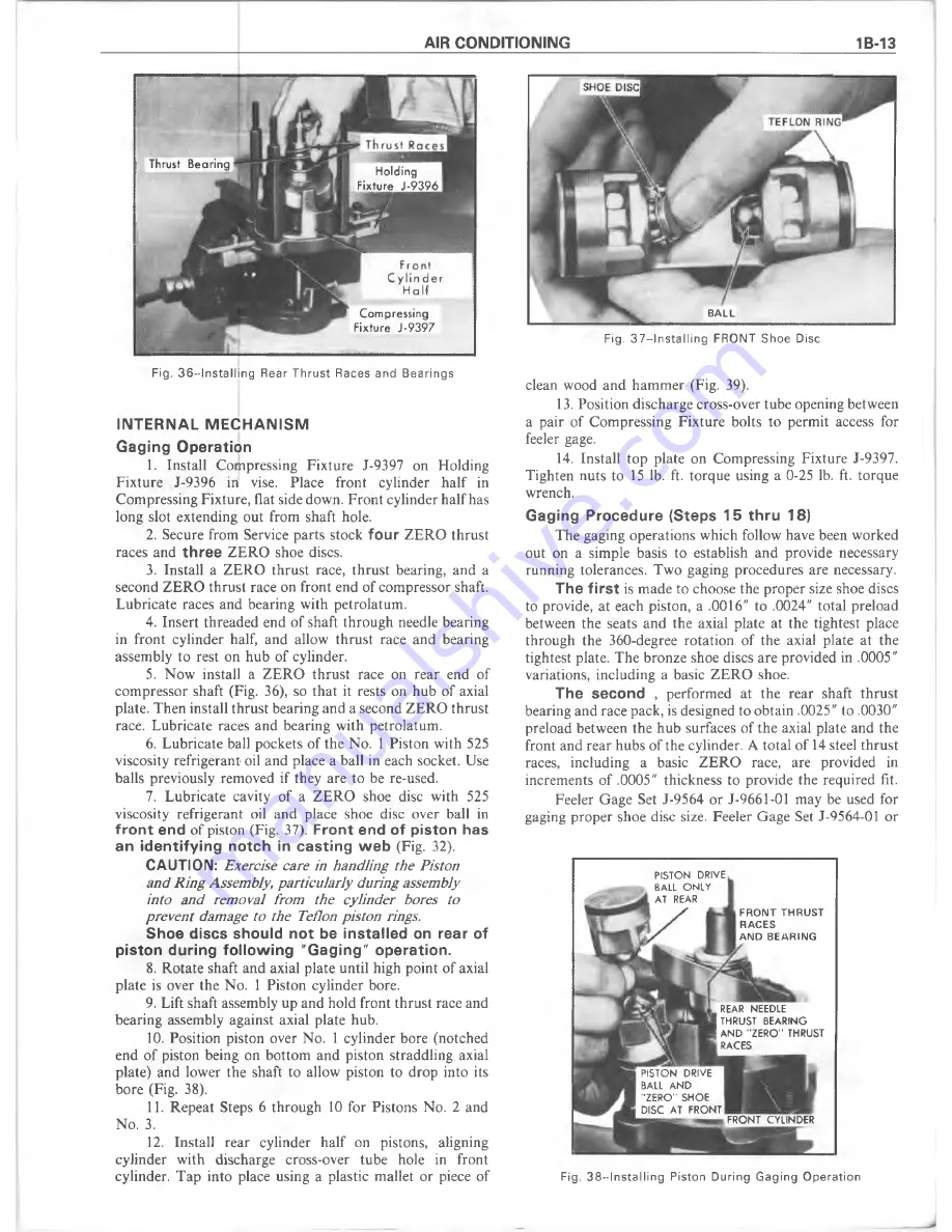
7. Lubricate cavity of a Z ER O shoe disc with 525
viscosity refrigerant oil and place shoe disc over ball in
front end
of piston (Fig. 37).
Front end of piston has
an identifying notch in casting web
(Fig. 32).
CAUTION:
Exercise care in handling the Piston
and Ring Assembly, particularly during assembly
into and removal from the cylinder bores to
prevent damage to the Teflon piston rings.
Shoe discs should not be installed on rear of
piston during following "Gaging" operation.
8. R otate shaft and axial plate until high point of axial
plate is over the No. 1 Piston cylinder bore.
9. Lift shaft assembly up and hold front thrust race and
bearing assembly against axial plate hub.
10. Position piston over No. 1 cylinder bore (notched
end of piston being on bottom and piston straddling axial
plate) and lower the shaft to allow piston to drop into its
bore (Fig. 38).
11. Repeat Steps 6 through 10 for Pistons No. 2 and
No. 3.
12. Install rear cylinder half on pistons, aligning
cylinder with discharge cross-over tube hole in front
cylinder. Tap into place using a plastic mallet or piece of
Holding
Fixture J-9
9396
Compressing
Fixture J-9397
B ALL
Fig. 3 7 —1 nsta lling FRONT Shoe Disc
clean wood and ham m er (Fig. 39).
13. Position discharge cross-over tube opening between
a pair of Compressing Fixture bolts to permit access for
feeler gage.
14. Install top plate on Compressing Fixture J-9397.
Tighten nuts to 15 lb. ft. torque using a 0-25 lb. ft. torque
wrench.
Gaging Procedure (Steps 15 thru 18)
The gaging operations which follow have been worked
out on a simple basis to establish and provide necessary
running tolerances. Two gaging procedures are necessary.
The first
is m ade to choose the proper size shoe discs
to provide, at each piston, a .0016" to .0024" total preload
between the seats and the axial plate at the tightest place
through the 360-degree rotation of the axial plate at the
tightest plate. The bronze shoe discs are provided in .0005"
variations, including a basic ZER O shoe.
The second
, performed at the rear shaft thrust
bearing and race pack, is designed to obtain .0025" to .0030"
preload between the hub surfaces of the axial plate and the
front and rear hubs of the cylinder. A total of 14 steel thrust
races, including a basic Z E R O race, are provided in
increments of .0005" thickness to provide the required fit.
Feeler Gage Set J-9564 or J-9661-01 may be used for
gaging proper shoe disc size. Feeler Gage Set J-9564-01 or
PISTON DRIVE
BALL ONLY
AT REAR
F R O N T T H R U S T
R A C E S
A N D B E A R IN G
REAR NEEDLE
THRUST BEARING
AND "ZERO" THRUST
RACES
PISTON DRIVE
BALL AND
'ZERO” SHOE
DISC AT FRONT
FRONT CYLINDER
Fig. 3 8 —1 nsta llin g Piston D u rin g G a g in g O p e ra tio n
Содержание 1977 10 Series
Страница 1: ......
Страница 2: ......
Страница 4: ......
Страница 6: ......
Страница 42: ......
Страница 65: ...STEERING 3B 23 Fig 3B 65 M easure Back and Remark Housing Fig 3B 67 Tighten Lock Nut...
Страница 86: ...4B 14 OVERHAUL MANUAL Fig 4B 28 Gear Teeth C ontact Pattern Check...
Страница 125: ...REAR AXLE DIFFERENTIAL 4B 53 Fig 18E Gear Teeth Contact Pattern Check...
Страница 156: ......
Страница 164: ...4C 8 OVERHAUL MANUAL Fig 4C 12 Gear Tooth Pattern Contact Pattern...
Страница 166: ......
Страница 194: ......
Страница 284: ......
Страница 320: ......
Страница 322: ...400 7A 2 OVERHAUL MANUAL Fig 7A 1C Side Cross Section Typical...
Страница 444: ...7B 64 OVERHAUL MANUAL Fig 7B 11S M od el 2 03 Transfer Case Exploded V iew...
Страница 458: ......
Страница 466: ......
Страница 467: ......
Страница 468: ......