


4C-6
OVERHAUL MANUAL
Fig. 4 C -9 —In s ta llin g In n e r P in io n C ore and R o lle r
6. Install drive pinion and inner bearing cone and roller
assembly in differential carrier.
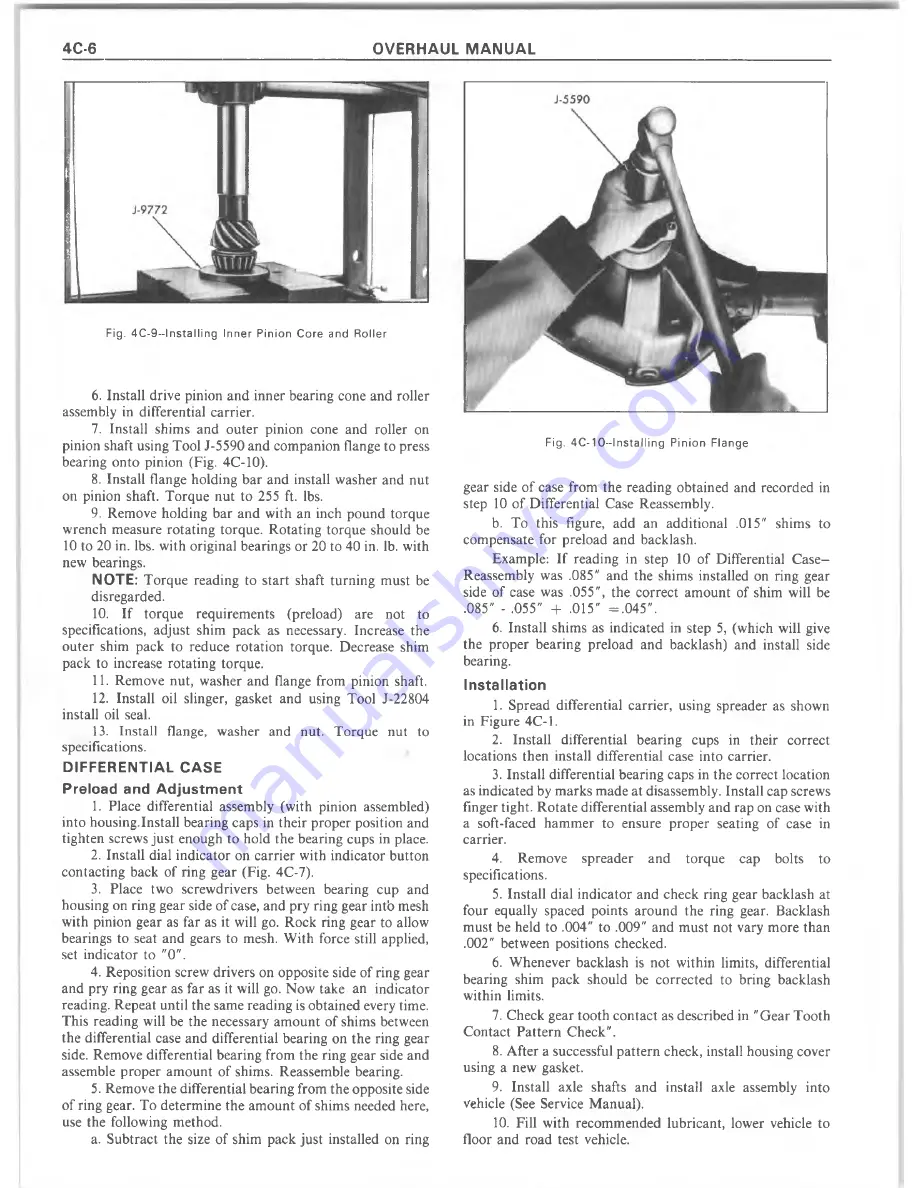
7. Install shims and outer pinion cone and roller on
pinion shaft using Tool J-5590 and companion flange to press
bearing onto pinion (Fig. 4C-10).
8. Install flange holding bar and install washer and nut
on pinion shaft. Torque nut to 255 ft. lbs.
9. Remove holding bar and with an inch pound torque
wrench measure rotating torque. Rotating torque should be
10 to 20 in. lbs. with original bearings or 20 to 40 in. lb. with
new bearings.
NOTE:
Torque reading to start shaft turning must be
disregarded.
10. If torque requirem ents (preload) are not to
specifications, adjust shim pack as necessary. Increase the
outer shim pack to reduce rotation torque. Decrease shim
pack to increase rotating torque.
11. Remove nut, washer and flange from pinion shaft.
12. Install oil slinger, gasket and using Tool J-22804
install oil seal.
13. Install flange, washer and nut. Torque nut to
specifications.
DIFFERENTIAL CASE
Preload and Adjustm ent
1. Place differential assembly (with pinion assembled)
into housing.Install bearing caps in their proper position and
tighten screws just enough to hold the bearing cups in place.
2. Install dial indicator on carrier with indicator button
contacting back of ring gear (Fig. 4C-7).
3. Place two screwdrivers between bearing cup and
housing on ring gear side of case, and pry ring gear intb mesh
with pinion gear as far as it will go. Rock ring gear to allow
bearings to seat and gears to mesh. W ith force still applied,
set indicator to "0".
4. Reposition screw drivers on opposite side of ring gear
and pry ring gear as far as it will go. Now take an indicator
reading. Repeat until the same reading is obtained every time.
This reading will be the necessary am ount of shims between
the differential case and differential bearing on the ring gear
side. Remove differential bearing from the ring gear side and
assemble proper am ount of shims. Reassemble bearing.
5. Remove the differential bearing from the opposite side
of ring gear. To determ ine the am ount of shims needed here,
use the following method.
a. Subtract the size of shim pack just installed on ring
Fig. 4 C - 10—1 n s ta llin g P in io n Flange
gear side of case from the reading obtained and recorded in
step 10 of Differential Case Reassembly.
b.
To this figure, add an additional .015" shims to
compensate for preload and backlash.
Example: If reading in step 10 of Differential C a se -
Reassembly was .085" and the shims installed on ring gear
side of case was .055", the correct am ount of shim will be
.085" - .055" + .015" = .0 4 5 ".
6.
Install shims as indicated in step 5, (which will give
the proper bearing preload and backlash) and install side
bearing.
Installation
1. Spread differential carrier, using spreader as shown
in Figure 4C-1.
2. Install differential bearing cups in their correct
locations then install differential case into carrier.
3. Install differential bearing caps in the correct location
as indicated by m arks made at disassembly. Install cap screws
finger tight. R otate differential assembly and rap on case with
a soft-faced ham m er to ensure proper seating of case in
carrier.
4.
Remove spreader and
torque cap bolts to
specifications.
5. Install dial indicator and check ring gear backlash at
four equally spaced points around the ring gear. Backlash
must be held to .004" to .009" and m ust not vary more than
.002" between positions checked.
6. W henever backlash is not within limits, differential
bearing shim pack should be corrected to bring backlash
within limits.
7. Check gear tooth contact as described in "G ear Tooth
Contact P attern Check".
8. After a successful pattern check, install housing cover
using a new gasket.
9. Install axle shafts and install axle assembly into
vehicle (See Service M anual).
10. Fill with recom m ended lubricant, lower vehicle to
floor and road test vehicle.
Содержание 1977 10 Series
Страница 1: ......
Страница 2: ......
Страница 4: ......
Страница 6: ......
Страница 42: ......
Страница 65: ...STEERING 3B 23 Fig 3B 65 M easure Back and Remark Housing Fig 3B 67 Tighten Lock Nut...
Страница 86: ...4B 14 OVERHAUL MANUAL Fig 4B 28 Gear Teeth C ontact Pattern Check...
Страница 125: ...REAR AXLE DIFFERENTIAL 4B 53 Fig 18E Gear Teeth Contact Pattern Check...
Страница 156: ......
Страница 164: ...4C 8 OVERHAUL MANUAL Fig 4C 12 Gear Tooth Pattern Contact Pattern...
Страница 166: ......
Страница 194: ......
Страница 284: ......
Страница 320: ......
Страница 322: ...400 7A 2 OVERHAUL MANUAL Fig 7A 1C Side Cross Section Typical...
Страница 444: ...7B 64 OVERHAUL MANUAL Fig 7B 11S M od el 2 03 Transfer Case Exploded V iew...
Страница 458: ......
Страница 466: ......
Страница 467: ......
Страница 468: ......