


Chapter 5 Detailed Function Introductions
143
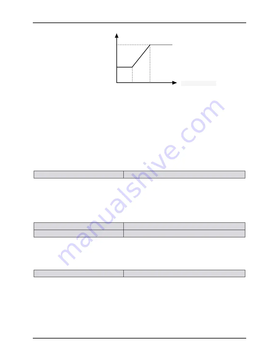
频率Hz
PI参数
P8.01、
P8.02
P8.04、
P8.05
P8.03
P8.06
Figure 5-8-1 PI parameters schematic diagram
You can adjust the speed dynamic response characteristics of vector control by setting the speed regulator
proportional coefficient and integral time. Increase the proportion gain, reduce the integration time can
accelerate loop dynamic response of the speed. If proportional gain is too large or integral time is too small,
it may make the system oscillation.
The proposed regulation method: If the factory parameters cannot meet the requirements, then adjust based
on the factory value parameters: first increase the proportion gain, guarantee system not oscillation; then
reduce integration time, let the system has fast response, small overshoot.
Tips:
If the PI parameter is not set appropriately, it may lead to speed overshoot too big. Even it produces
overvoltage failure when the overshoot falls.
P8.07 Speed loop filtering time
Setting range: 0.000s
~
0.100s [0.030s]
Explanation:
In the vector control mode, the output of the speed loop regulator is torque current command. The
parameters are used for the torque command filter. The parameters require no adjustment in general. When
the speed fluctuation is big, it may appropriately increase the filtering time. If the motor oscillation, it
should appropriately reduce the parameter.
If the speed loop filter time constant is small, the frequency inverter output torque may change greatly, but
the response is fast.
P8.08 Current loop proportional gain
Setting range: 0.1
~
9.9[1.0]
P8.09 Current loop integral time
Setting range: 0.001
~
1.000s [0.100]
Explanation:
The vector control will control the motor output current and track the current command value. Here, set
current control proportional and integral gain. Usually, you do not need change the factory value. When the
coil inductance is large, you can increase the P gain. When the coil inductance is small, you can reduce the P
gain. If I gain is set too large, it will cause current oscillation.
P8.10 Torque control mode
Setting range: 0~2 [0]
0: Operation according to the speed control
mode
1: Operation according to the torque control mode
2: Operation according to the torque motor
mode
Explanation:
When the setting is 0, the frequency inverter outputs according to the setting frequency. The output torque
matches with the load torque automatically, but the output torque is limited by the torque upper limit. When
the load torque is larger than the setting torque upper limit, the frequency inverter output torque is limited.
The output frequency is different from the setting frequency.
PI parameter
Frequency HZ
Содержание 6000S series
Страница 1: ......
Страница 74: ...Chapter 4 Parameter Index 73 P6 18 Stochastic swing ratio MIN Stochastic swing ratio MIN 0 1 10 0 0 1 0712...
Страница 221: ......


