18-18
IM 701240-01E
Item
Specifications
Compatible probes/cables Voltage probe (10:1 safety probe): Recommended
700929 (10:1 safety probe) .20 to 45 pF: For measuring 600 Vpeak or less
Current probe (power can be supplied from the SL1400)
701930 (150 A), 701931 (500 A), and 701933 (30 A)
High voltage differential probe (connect the GND cable provided with the probe to the SL1400 case)
700924 (1000:1, 100:1/1400 Vpeak): For measuring 1400 Vpeak or less
Connection cable (for high voltage 1:1)
701901 (isolated type BNC-safety alligator clip adapter
×
2: For measuring 200 Vpeak or less),
a separate alligator clip (701954) is required
Connection cable (for low voltage 1:1)
366926 (non-isolated type BNC-alligator clip
×
2: For measuring low voltage less than or equal
to 42 Vpeak)
1 Value measured under standard operating conditions (section 18.11).
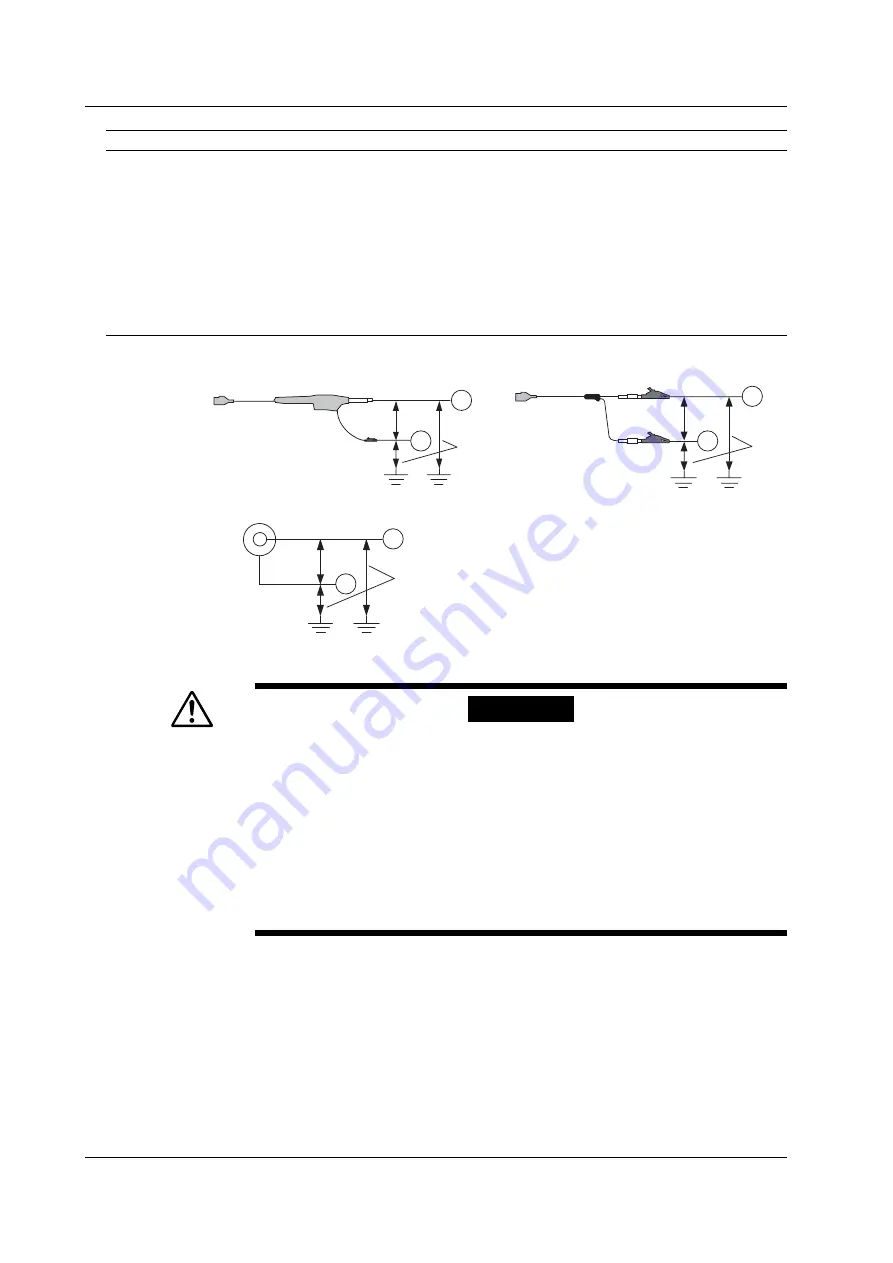
Withstand voltage: 1500 Vrms for 1 minute
Allowable transient surge voltage:
±
2100 Vpeak
(between earth and input)
Combined with the 700929
2
3
700929
Combined with the 701954
H
L
Direct input (cable that does not comply with the safety standards)
6
7
BNC
H
L
701901
701954
4
H
L
5
8 Typical value represents a typical or average value. It is not strictly warranted.
WARNING
• Do not apply input voltage exceeding the maximum input voltage, withstand
voltage, or allowable surge voltage.
• To prevent electric shock, be sure to furnish protective earth grounding of the
SL1400.
• To prevent electric shock, be sure to fasten the module screws. Otherwise, the
electrical and mechanical protection functions will not be activated.
• Avoid continuous connection under an environment in which the surge voltage
voltage may occur.
• To prevent electric shock, be sure to connect the GND lead of the differential
probe (700924/700925) to the SL1400.
18.12 Module Specifications


