5-1
IM 701240-01E
3
2
1
4
5
6
7
8
9
10
11
12
13
14
15
16
17
18
App
Index
Horizontal and Vertical Axes
5.1
Turning Channels ON/OFF
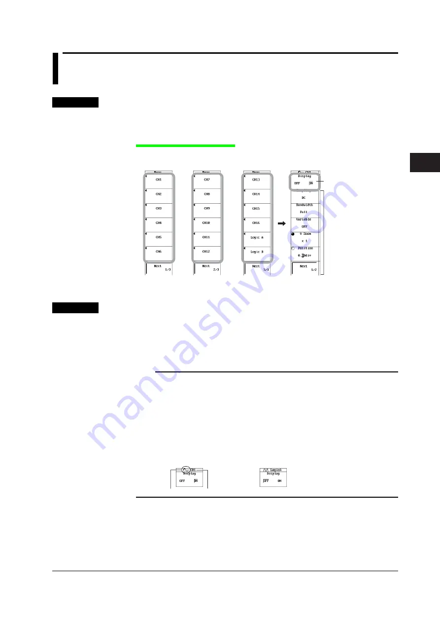
Procedure
1.
Press
CH
.
2.
Press one of the soft keys from
CH1 to CH16
,
Logic A
, and
Logic B
.
Turning the Display ON/OFF
3.
Press the
Display
soft key to select ON or OFF.
Press the
Next
soft key to display the next
menu.
The displayed menu varies
depending on the installed
input module.
CH1 to CH16, Logic A,
or
Logic B
Turn the display
Explanation
Select a channel from CH1 to CH16, Logic A, and Logic B, and turn ON/OFF the input
waveform display.
• CH1 to CH16, Logic A, and Logic B waveforms can be displayed simultaneously.
• When you are entering the settings of a selected channel, the channel name and the
specified measurement range are displayed at the upper left of the screen.
Note
•
The screen can be split into up to 16 display areas using the DISPLAY menu (section 8.1).
Scale values (section 8.9) and waveform labels (section 8.10) can also be displayed.
•
When displaying history waveforms or waveforms recalled from the PC card, the waveforms
applied to the channels cannot be displayed. To compare waveforms, use the snapshot
function.
•
Channels that do not have input modules installed cannot be turned ON.
•
A waveform icon is displayed to the left of the channel name at the top of the CH1 to CH16 or
Logic A/B setup menu. The icon color is the same as the color of the displayed waveform
(see section 16.3). The icon shape varies depending on the channel setup menu as follows:
CH1 to CH16
Logic A/B
Channel name
Waveform icon
Chapter 5
Horizontal and Vertical Axes


