6*28 Frame, suspension and final drive
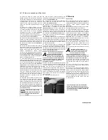
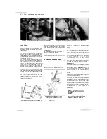
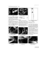
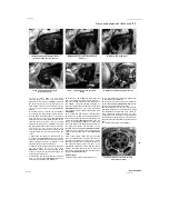
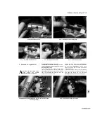
15.3 Linkage arm/shaft alignment -TRX
models
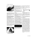
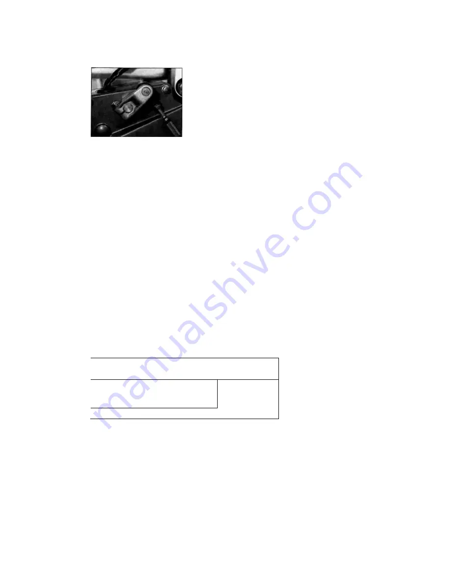
lever linkage arm pinchbolt and remove the arm
from the shaft, noting the alignment of the punch
mark with the slit in the clamp
(see illustration).
If no mark is visible, make your own before
removing the arm so that it can be correctly
aligned with the shaft on installation. Unscrew the
bolts securing the outer front sprocket cover and
remove the cover, then unscrew the bolts
securing the inner sprocket cover, noting the clip
secured by the top rear bolt, and remove the
cover.
4 Slip the chain off the front sprocket and
remove it from the bike.
Cleaning and wear check
5
Soak the chain in paraffin (kerosene) for
approximately five or six minutes.
Caution: Don't
use gasoline (petrol), solvent or other
cleaning fluids. Don't use high-pressure
water. Remove the chain, wipe it off, then
blow dry it with compressed air immediately.
The entire process shouldn't take longer than
ten minutes - if it does, the O-rings in the
chain rollers could be damaged.
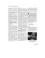
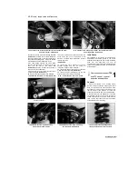
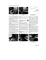
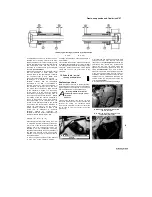
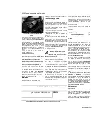
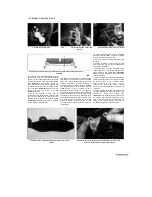
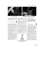
6 Once the chain has been cleaned and dried,
check it for wear by measuring a 10-link length
with the chain taught; anchor one end of the
chain and hold the other end tensioned whilst the
measurement is taken
(see illustration).
Compare the result the wear limits at the
beginning of this Chapter. Note that chains do
not wear evenly, so take measurements at
various points in the chain's run.
Installation
7 Installation is the reverse of removal. On
completion adjust and lubricate the chain
following the procedures described in Chapter 1.
Riveted link type chain
Removal
Note:
The riveted (soft) link can be identified by
its identification markings on the side plate and
usually slightly different colour. Also the staked
ends of the link's two pins look as if they have
been deeply centre-punched, instead of peened
over as with all other pins.
8 Locate the joining link in a suitable position to
work on by rotating the back wheel; midway
between the sprockets is ideal.
9 Slacken the drive chain as described in
Chapter 1.
10
Split the chain at the joining link using an
approved chain breaker tool intended for
motorcycle use. There are a number of types
available for motorcycle use and it is important to
follow carefully the instructions supplied with the
tool - see 7bo/s
and Workshop Tips
in the
Reference section for a typical example. Remove
the chain from the bike, noting its routing through
the swingarm.
Cleaning and wear check
11
See Steps 5 and 6.
Installation
Warning: NEVER install a drive
chain which uses a clip-type master
(split) link. If you do not have access
to a chain riveting tool, have the chain
fitted by a Yamaha dealer.
12 Remove the engine sprocket cover as
described in Steps 2 or 3, as applicable.
13 Thread the chain into position, making sure
that it takes the correct route around the
swingarm and sprockets and leave the two ends
in a convenient place to work on. Obtain a new
soft link - never attempt to reuse an old link.
14 Install the new soft link complete with an O-
ring on each of its pins through the chain ends
from the inside of the chain. Install an O-ring over
the pin ends and fit the side plate with its
identification marks facing out; use the chain tool
to press the side plate into position.
15
Stake the new link pins using the chain
riveting tool, following carefully the instructions of
both the chain manufacturer and the tool
manufacturer. Refer to
Tools and Workshop Tips
in the Reference section for
chain riveting details using a typical commercially
available tool.
16
After riveting, check the soft link pin ends for
any signs of cracking. If there is any evidence of
cracking, the soft link, O-rings and side plate
must be removed and the procedure repeated
with a new soft link.
17 Install the sprocket cover in a reverse of the
removal procedure. Adjust and lubricate the
chain following the procedures described in
Chapter 1.
16 Sprockets-
|k
check and replacement
|s
Check
1
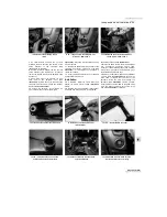
On TDM and XTZ models, unscrew the bolts
securing the outer front sprocket cover and
remove the cover
(see illustration 15.2a).
Unscrew the gearchange lever linkage arm
pinchbolt and remove the arm from the shaft,
noting the alignment of the punch mark with the
slit in the clamp
(see illustration 15.2b).
If no
mark is visible, make your own before removing
the arm so that it can be correctly aligned with the
shaft on installation. Unscrew the bolts securing
the inner sprocket cover, on TDM models noting
the clip secured by the top rear bolt, and remove
the cover
(see illustration 15.2c).
2
On TRX models, unscrew the gearchange
lever linkage arm pinchbolt and remove the arm
from the shaft, noting the alignment of the punch
mark with the slit in the clamp
(see illustration
15.3).
If no mark is visible, make your own before
removing the arm so that it can be correctly
aligned with the shaft on installation. Unscrew the
bolts securing the outer front sprocket cover and
remove the cover, then unscrew the bolts
securing the inner sprocket cover, noting the clip
secured by the top rear bolt, and remove the
cover.
3 Check the wear pattern on both sprockets
(see
illustration 1.7 in Chapter 1).
If the sprocket
teeth are worn excessively, renew the chain and
both sprockets as a set. Whenever the sprockets
are inspected, the drive chain should be
inspected also (see Chapter 1). If you are
renewing the chain, renew the sprockets as well.
4 Adjust and lubricate the chain following the
procedures described in Chapter 1.
Caution: Use
only the recommended lubricant.
Replacement
Front sprocket
5
On TDM and XTZ models, unscrew the
bolts securing the outer front sprocket cover
and remove the cover
(see illustration 15.2a).
Unscrew the gearchange lever linkage arm
pinchbolt and remove the arm from the shaft,
noting the alignment of the punch mark with
the slit in the clamp
(see illustration 15.2b). If
Scaned by Stalker
'II ll"Mll"ll ll'tT ll'l I M"l I L
L
ILL-U.
(2^3Sr2H°3S5K£^H
S33
15.6 Check the amount of stretch by measuring
a
10-link length as shown
A

