5*4 Ignition system
QXlk
-
©♦
J
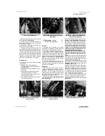
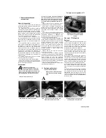
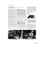
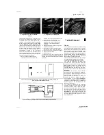
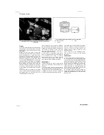
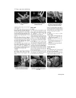
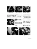
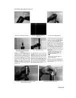
3.7b Coil secondary resistance test - 1996-on TDM and all TRX models
3.8 Measure the resistance of the spark
plug cap
primary circuit terminal
(see illustration).
If the
reading obtained is not within the range shown in
the Specifications, it is likely that the coil is
defective.
8 If the reading is as specified, measure the
resistance of the spark plug cap by connecting
the meter probes between the HT lead socket in
the cap and the spark plug contact in the cap
(see illustration).
If the reading obtained is not
as specified, renew the spark plug caps.
9 Should any of the above checks not produce
the expected result, have your findings confirmed
by a Yamaha dealer. If the coil is confirmed to be
faulty, it must be renewed; the coil is a sealed
unit and cannot therefore be repaired.
Removal
10
Remove the left-hand side cover (XT2
models) or the seat (all other models) (see
Chapter 8). Disconnect the battery negative (-ve)
lead.
11
On TDM and TRX models, the coil/s is/are
mounted on the inside of the frame behind the
steering head - remove the fuel tank and the air
filter housing for access (see Chapter 4)
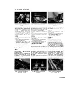
(see
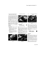
illustrations 3.4a and b).
On XTZ models, the
coil is mounted underneath the rear of the fuel
tank - remove the tank for access (see Chapter
4)
(see illustration 3.4c).
12
Disconnect the primary circuit electrical
connectors from the coil and disconnect the HT
lead(s) from the spark plug(s). Mark the
locations of all wires and leads before
disconnecting them.
13
Unscrew the two bolts or screws securing
each coil, noting any spacers, and on TRX
models the earth wire secured by one of the
screws,
and
remove
the
coils
(see
illustrations 3.4a, b and c).
Note the routing
of the HT leads.
Installation
14 Installation is the reverse of removal.
Make sure the wiring connectors and HT
leads are securely connected.
Pick-up coil
-
check and replacement
Check
1 On TDM and TRX models remove the seat,
and on XTZ models remove the left-hand side
cover (see Chapter 8). Disconnect the battery
negative (-ve) lead.
2 On TRX models, remove the side covers (see
Chapter 8).
3 Trace the pick-up coil/alternator wiring from
the top of the alternator cover and disconnect it
at the connector with the white/green and
white/red (early TDM models) or green/white and
blue/yellow (all other models) wires
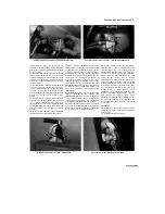
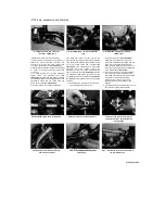
(see
illustrations).
Using a multimeter set to the
ohms x 100 scale, measure the resistance
between the terminals on the pick-up coil side of
the connector.
4 Compare the reading obtained with that given
in the Specifications at the beginning of this
Chapter. The pick-up coil must be renewed if the
reading obtained differs greatly from that given,
particularly if the meter indicates a short circuit
(no measurable resistance) or an open circuit
(infinite, or very high resistance).
5 If the pick-up coil is thought to be faulty, first
check that this is not due to a damaged or broken
wire from the coil to the connector; pinched or
broken wires can usually be repaired.
Replacement
6 The pick-up coil is wired integrally with the
alternator stator, which means that the stator
must be removed and renewed along with the
coil if the coil is faulty. However it is worth
checking with a Yamaha dealer to see if the coil
can be obtained separately and wired into the
loom to avoid the extra expense of paying for a
stator as well.
7 Refer to Chapter 9 for details of alternator
stator/pick-up coil assembly removal.
5 Ignitor unit
- check, removal
and installation
Check
1 If the tests shown in the preceding or following
Sections have failed to isolate the
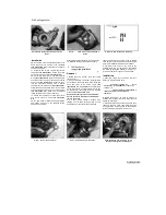
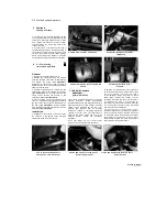
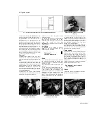
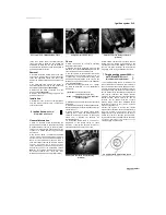
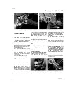
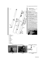
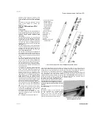
4.3a Pick-up coil wiring connector
(arrowed) - TOM models
4.3b Pick-up coil wiring connector
(arrowed) - TRX models
4.3c Pick-up coil wiring connector
(arrowed) - XTZ models
Scaned by Stalker
I

