UNREGISTERED VERSION OF PICTURED
UNREGISTERED VI
Ignition system 5»5
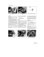
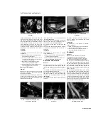
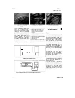
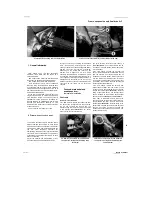
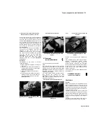
5.3a Ignitor unit - TDM and TRX models
5.3b Ignitor unit - XTZ models
5.4 Disconnect the wiring connectors
(arrowed)
cause of an ignition fault, it is possible that the
ignitor unit itself is faulty. No test details are
available with which the unit can be tested on
home workshop equipment. Take the machine to
a Yamaha dealer for testing.
Removal
2 On TDM and TRX models remove the seat,
and on XTZ models remove the left-hand side
cover and right-hand fairing side panel (see
Chapter 8). Disconnect the battery negative (-ve)
lead.
3 On TDM and TRX models the ignitor is
mounted under the seat, and on XTZ models it is
mounted in the fairing
(see illustrations).
4
Disconnect the wiring connectors from the
ignitor unit
(see illustration).
5
Remove the screws securing the ignitor unit
and remove the unit.
Installation
6 Installation is the reverse of removal. Make
sure the wiring connectors are correctly and
securely connected.
6 Ignition timing
- general
information and check
General information
1
Since no provision exists for adjusting the
ignition timing and since no component is subject
to mechanical wear, there is no need for regular
checks; only if investigating a fault such as a loss
of power or a misfire, should the ignition timing
be checked.
2 The ignition timing is checked dynamically
(engine running) using a stroboscopic lamp. The
inexpensive neon lamps should be adequate in
theory, but in practice may produce a pulse of
such low intensity that the timing mark remains
indistinct. If possible, one of the more precise
xenon tube lamps should be used, powered by
an external source of the appropriate voltage.
Note:
Do not use the machine's own battery as
an incorrect reading may result from stray
impulses within the machine's electrical system.
Check
3
Warm the engine up to normal operating
temperature then stop it.
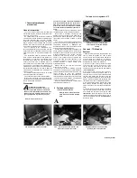
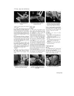
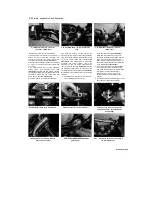
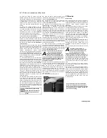
4 Unscrew the timing inspection plug from the
alternator cover
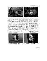
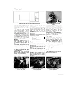
(see illustration).
Discard the
cover O-ring as a new one must be used.
5 The timing mark on the alternator rotor which
indicates the firing point at idle speed for the no.
1 cylinder is a 'I I" mark. The static timing mark
with which this should align is the notch in the
threads for the inspection plug on the alternator
cover
(see illustration).
6
Connect the timing light to the no. 1 cylinder
HT lead as described in the manufacturer's
instructions.
[JfJJJtM
The timing marks can be
"
highlighted with white paint
HllUT
to make them
more visible
under the
stroboscope light.
7
Start the engine and aim the light at the static
timing mark.
8 With the machine idling at the specified speed,
the static timing mark should lie between the two
vertical lines 'I I'.
9 Slowly increase the engine speed whilst
observing the 'I I' mark. The mark should move
clockwise, increasing in relation to the engine
speed until it reaches full advance (no
identification mark).
10 As already stated, there is no means of
adjustment of the ignition timing on these
machines. If the ignition timing is incorrect, or
suspected of being incorrect, one of the
ignition system components is at fault, and the
system must be tested as described in the
preceding Sections of this Chapter. 11 When the
check is complete, install the timing inspection
plug using a new O-ring and tighten it securely.
7 Throttle position sensor (1996-
%
on TDM and TRX)-
check, «
adjustment and replacement S*
1 The throttle position sensor is located on the
side of the left-hand carburettor and is keyed to
the end of the throttle operating shaft. The sensor
provides the ignitor unit with information relating
to throttle opening and the ignitor is thus able to
set the ignition timing accordingly to produce the
best running conditions and cleaner exhaust
emissions. Not surprisingly it is essential that the
throttle position sensor should be set up
correctly. Do not tamper with the sensor's
position unless it has been disturbed during
carburettor overhaul or poor running problems
have been experienced.
2 When the engine is running, the throttle
position sensor performs its own self-diagnosis in
the event of failure or faulty wiring. When this
diagnosis occurs, the tachometer will be seen to
display zero rpm for 3 seconds, then 3000 rpm
for 2.5 seconds, then the actual engine speed for
3 seconds, whereupon it will repeat the cycle
until the engine is switched off.
Staged by Stalker
I
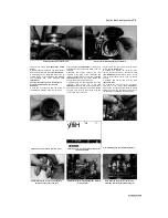
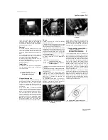
6.4 Unscrew the timing inspection plug
(arrowed)
6.5 Ignition timing marks at idle speed

