r UNREGISTERED VERSION OF PICTURE-DESK
Engine, clutch and transmission 2*11
3 Before commencing work, read through the
appropriate section so that some idea of the
necessary procedure can be gained. When
removing components it should be noted that
great force is seldom required, unless specified.
In many cases, a component's reluctance to be
removed is indicative of an incorrect approach or
removal method - if in any doubt, re-check with
the text.
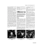
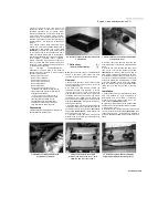
4 An engine support stand made from short
lengths of 2 x 4 inch wood bolted together into a
rectangle will help support the engine
(see
illustration).
The perimeter of the mount should
be just big enough to accommodate the sump
within it so that the engine rests on its crankcase.
5 When disassembling the engine, keep 'mated'
parts together (including gears, cylinders,
pistons, connecting rods, valves, etc. that have
been in contact with each other during engine
operation). These 'mated' parts must be reused
or renewed as an assembly.
6 A
complete
engine/transmission
disassembly should be done in the following
general order with reference to the appropriate
Sections of this Chapter.
Remove the valve cover
Remove the camshafts
Remove the cylinder head
Remove the cylinder block
Remove the pistons
Remove the clutch
Remove the alternator/pick-up coil
assembly (see Chapter 9) Remove the
starter motor (see Chapter 9) Remove the
gearchange mechanism
external components Remove the oil
pumps Remove the oil sump Separate
the crankcase halves Remove the
crankshaft Remove the transmission
shafts Remove the selector drum and
forks Remove the balancer shafts
Reassembly
7 Reassembly is accomplished by reversing the
general disassembly sequence.
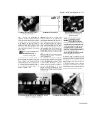
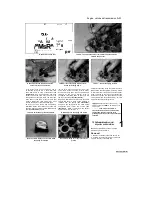
6.4 An engine support made from pieces of 2
x 4 inch wood
7 Valve cover
-
&>
removal and installation
|§
Note:
The valve covers can be removed with the
engine in the frame. If the engine has been
removed, ignore the steps which do not apply.
Removal
1 Remove the fuel tank, the air filter housing
and the carburettors (see Chapter 4). Drain the
coolant (see Chapter 1).
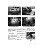
2 On TDM and TRX models, remove the
thermostat housing (see Chapter 3). When
removing the housing, remove it along with the
pipe that bolts onto the valve cover, rather than
separating the hose from the pipe. The pipe is
secured by a bolt - make sure the pipe O-ring
does not fall into the engine when easing out the
pipe
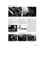
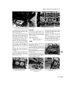
(see illustration).
Discard the O-ring as a
new one must be used.
3 On XTZ models, unscrew the bolt securing the
coolant pipe to the valve cover and ease the pipe
out, making sure the O-ring does not
fall into
the
engine
(see illustration 7.2).
Discard the O-ring
as a new one must be used.
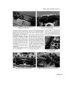
4 If required, release the clamp securing the
breather hose to the valve cover and detach the
hose
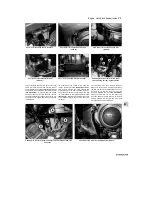
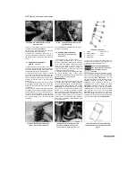
(see illustration).
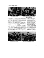
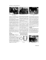
7.2 Unscrew the bolt (arrowed) and detach the
pipe from the cover
5
Pull the spark plug caps off the plugs and
secure them clear of the engine, noting which fits
where.
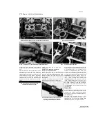
6 Unscrew the bolts securing the valve cover
then lift the cover off the cylinder head
(see
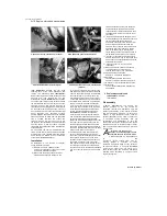
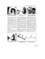
illustration).
On 1996-on TDM models and all
TRX models, note which bolt fits where as some
are of different length. If the cover is stuck, do not
try to lever it off with a screwdriver. Tap it gently
around the sides with a rubber hammer or block
of wood to dislodge it. Also remove the gasket.
Note the rubber spark plug hole gaskets fitted
inside the cover and remove them if they are
loose.
Installation
7 Examine the valve cover gasket and the spark
plug hole gaskets for signs of damage or
deterioration and renew them if necessary.
Similarly check the rubber grommets on the
cover bolts
(see illustration 7.10b).
8
Clean the mating surfaces of the cylinder head
and the valve cover with lacquer thinner, acetone
or brake system cleaner.
9 Install the gasket onto the valve cover, making sure
it fits correctly into the groove
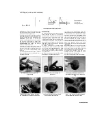
(see illustration).
Also
fit the spark plug hole
o
gaskets. Use a few dabs of
grease to keep the gaskets in place while the cover is
fitted.
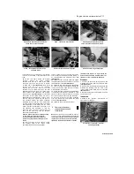
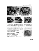
7.4 Release the clamp and detach the
breather hose (arrowed)
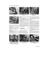
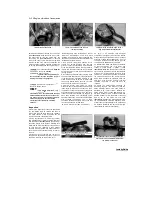
7.6 Unscrew the valve cover bolts
(arrowed) and remove the cover - early
TDM and XTZ type cover shown
7.9 Fit the main gasket and the spark plug
hole gaskets (arrowed) into their grooves
Scaned by Stalker

