Engine, clutch and transmission 2*45
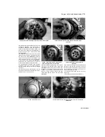
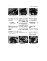
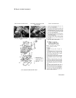
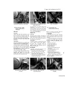
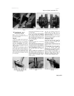
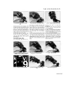
24.2 Draw the cam chain out of the engine
24 Cam chain and guides -
removal, inspection and
installation
Removal
Cam chain
1
Remove the valve cover (see Section 7), the
cam chain tensioner (see Section 9), the cam
chain top guide and the camshaft sprockets (see
Section 8), and the oil pumps (see Section 20).
2 Feed the cam chain down through the tunnel
and draw it out of the oil pump housing
(see
illustration).
Chain guides
3
The cam chain top guide can be unbolted from
the cylinder head after the valve cover has been
removed (see Section 7)
(see illustration
8.4).
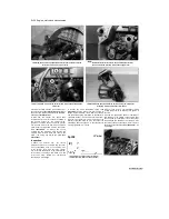
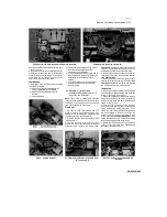
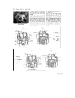
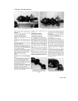
4 The cam chain front guide can be lifted from
the cylinder head after the cam chain tensioner
(see Section 9) and the exhaust camshaft
sprocket have been removed (see Section 8)
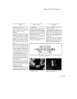
(see illustrations).
Note which way up and
round the guide fits and how it locates.
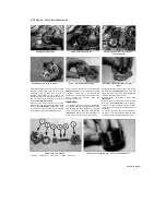
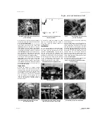
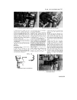
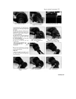
5 The cam chain rear guide is secured by a pivot
pin, which is located behind one of the 6 mm
crankcase bolts. Remove the cam chain
tensioner (see Section 9), the inlet camshaft
sprocket (see Section 8) and the oil pump
24.4a Note how the front guide locates in the
cylinder head (arrow)
...
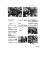
cover (see Section 20). Unscrew the bolt
(see
illustration).
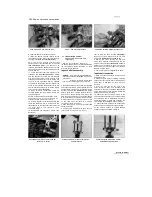
As the pivot pin is set deep, its
centre is threaded to accept a 5 mm bolt. Thread
the bolt into the pin, then draw out the bolt with
the pin attached and lift the guide out of the top
of the tunnel
(see illustrations).
Inspection
Cam chain
6
Check the chain for binding, kinks and any
obvious damage and renew it if necessary.
Check the camshaft sprocket teeth for wear
and renew the cam chain and sprockets as a
set if necessary (see Chapter 8).
Chain guides
7
Check the guides for excessive wear, deep
grooves, cracking and other obvious damage,
and renew them if necessary. Check the
condition of the pivot hardware on the rear
guide and renew any components that are
damaged or deteriorated.
Installation
8 Installation of the chain and guides is the
reverse of removal, noting the following:
a) Apply engine oil to the faces of the guides, to
the rear guide pivot pin, and to the chain.
b) Use a piece of bent wire to hook up the
cam chain and draw it up the tunnel.
cj Tighten the 6 mm crankcase bolt for the
rear guide to the torque setting specified at
the beginning of the Chapter.
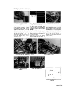
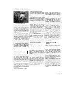
24.4b
...
and lift it out
25 Crankcase halves -
separation and reassembly
Note:
To separate the crankcase halves, the
engine must be removed from the frame.
Separation
1
To access the connecting rods, crankshaft,
bearings, transmission shafts and the selector
drum and forks, the crankcase must be split into
two parts.
2 To enable the crankcases to be separated, the
engine must be removed from the frame (see
Section 5). Before the crankcases can be
separated the following components must be
removed:
a) Valve cover (Section 7).
b) Cylinder head (Section 10).
c) Cylinder block (Section 13).
d) Pistons (Section 14).
e) Clutch (Section 16).
f) Starter clutch and idle/reduction gear
(Section 18).
g) Gearchange mechanism external
components (Section 19).
h) Oil pumps (Section 20).
i) Cam chain and guides (Section 24).
j) Oil tank (1996-on TDM models and all
TRX models) (Section 21). k) Oil sump
(Section 22). I) Balancer shafts (Section 23). m)
Water pump (Chapter 3). n) Starter motor (if
required) (Chapter 9).
2
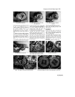
24.5a Unscrew the crankcase bolt
(arrowed)...
24.5b ... then thread a 5 mm bolt into the
head of the pivot pin ...
.. then withdraw the pin and lift out
the guide
Staned by Stalker

