1.12 Every 4000 miles (6000 km) or 6 months
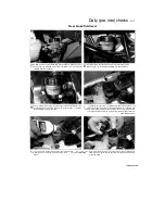
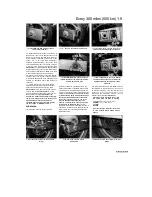
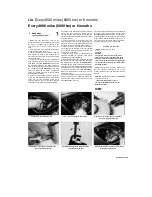
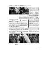
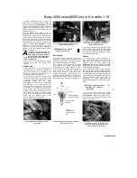
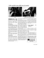
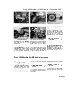
4.7a On XTZ models, detach the vacuum hose (arrowed).
4.7b ... and remove the blanking plug (arrowed)
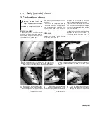
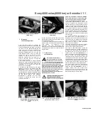
4.12 Carburettor synchronisation screw
(arrowed) - air filter housing removed for
clarity
manifold between the carburettor and the
cylinder head to make sure you have the correct
one. If access is not too restricted, the hoses can
be
detached
from
the
intake
manifolds
themselves.
7 On XTZ models, release the clamps securing
the vacuum hose and the blanking plug to the
take-off stubs on the inlet manifolds between the
carburettor and the cylinder head and detach the
hose and plug
(see illustrations).
8 On TDM and TRX models, connect the
gauges to the vacuum hose ends. On XTZ
models, connect the gauge hoses to the takeoff
stubs on the inlet manifolds. Make sure there are
no air leaks as false readings will result.
9 Arrange a temporary fuel supply, either by
using a small temporary tank or by using extra
long fuel pipes to the now remote fuel tank.
Alternatively, position the tank on a suitable
base on the motorcycle, taking care not to
scratch any paintwork, and making sure that
the tank is safely and securely supported. If
using the main tank, switch the tap to ON or
RES on TDM and XTZ models, and to PRI on
TRX models.
10 Start the engine and let it idle. If the gauges
are fitted with damping adjustment, set this so
that the needle flutter is just eliminated but so
that they can still respond to small changes in
pressure.
11 The vacuum readings for both cylinders
should be the same. If the vacuum readings
differ, proceed as follows.
12 The carburettors are adjusted by turning the
synchronising screw situated in-between the
carburettors, in the throttle linkage
(see
illustration). Note:
Do not press down on the
screw whilst adjusting it, otherwise a false
reading will be obtained.
When the carburettors
are synchronised, open and close the throttle
quickly a few times to settle
the linkage, and recheck the gauge readings,
readjusting if necessary.
13 When the adjustment is complete, recheck
the vacuum readings, then adjust the idle speed
(see Section 3) until the speed listed in this
Chapter's Specifications is obtained. Detach the
temporary fuel supply, then remove the gauges.
Refit the vacuum hoses and/or blanking plugs as
required by your model (see Steps 9, 10 and 11).
14 Install the fuel tank (see Chapter 4).
1 Remove the fuel tank (see Chapter 4). On XTZ
models, also remove the air filter housing (see
Chapter 4); it is possible to remove the covers
and elements with the housing in situ but access
to the screws is restricted and the screws are
easily dropped.
2 On TDM and TRX models remove the screws
securing the air filter cover to the filter housing,
then remove the cover and withdraw the filter
element from the housing
(see illustrations).
3
On XTZ models, there are two filter elements,
each fitted integral with its cover on the front of
the housing
(see illustrations).
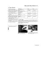
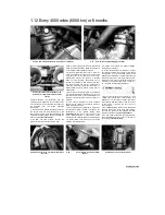
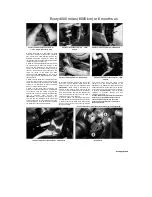
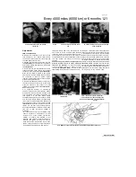
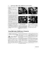
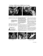
5.2a Remove the screws (arrowed) and lift off
the cover...
5.2b ..
then withdraw the element (TDM
shown)
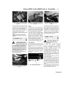
5.3a Remove the screws (arrowed)...
Scaned by Stalker

