8*6 Bodywork
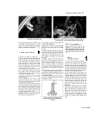
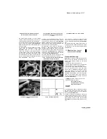
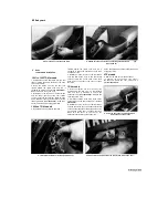
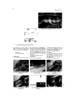
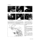
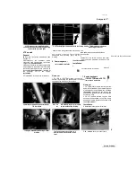
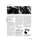
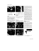
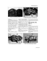
5.10a Unscrew the nuts (arrowed).
5.10b ... withdraw the screws and
remove the mirrors...
5.10c ... and the rubber pad
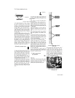
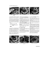
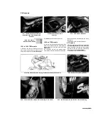
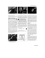
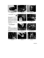
5.11a Disconnect the headlight wiring
connector (arrowed)...
5.11b ... the auxiliary light wiring
connector (arrowed)...
5.11c
.. and the turn signal wiring
connectors
turn signal to the fairing. Thread the nut off the
wires and remove each turn signal assembly 8
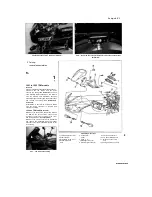
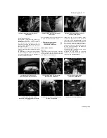
Remove the two screws and the four nuts securing
the fairing and headlight to the bracket. Carefully
draw the fairing forward and
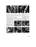
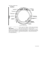
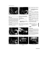
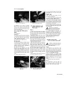
5.12 Fairing mounting screws (A) and nuts (B)
remove it along with the headlight. If required, lift
the headlight out of the fairing.
Installation
9
Installation is the reverse of removal. Make
sure the wiring connectors are correctly and
securely connected. Check that the headlight,
auxiliary light and turn signals are all working.
TRX models
Removal
10
Unscrew the nuts securing the rear view
mirrors to the fairing bracket and remove the
mirrors along with the rubber pads
(see
illustrations).
11
Disconnect the headlight, auxiliary light and
turn signal wiring connectors
(see illustrations).
12
Remove the screw securing each side of the
fairing and the four nuts securing the fairing and
headlight to the bracket
(see illustration).
Carefully draw the fairing forward and remove it
along with the headlight. If required, lift the
headlight out of the fairing.
Installation
13
Installation is the reverse of removal.
Make sure the arrow on each rubber pad for
the mirror is on the outside and pointing
forward
(see
illustration
5.10c).
Make
sure the wiring connectors are correctly
and securely connected. Check that the
headlight, auxiliary light and turn signals are
all working.
Scaned by Stalker
6
Remove the remaining screws securing the
cockpit trim panel and remove the panel.
7 Reach inside the fairing and disconnect the
headlight, auxiliary light and turn signal wiring
connectors. Unscrew the nut which retains each

