background image

Engine, clutch and transmission 2«53


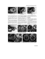
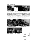
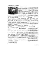
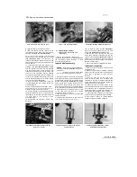
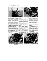
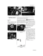
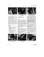
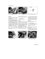
30.2 Lift out the output shaft


30.4a Draw out the shaft once the retainer screws have been 

removed


upper crankcase, making sure all bearings 
remain in place 

(see illustration 29.3).


29  Fit   

the   connecting   rods   onto   the 

crankshaft (see Section 28).


30  Reassemble the crankcase halves (see 
Section 25). 

30 Transmission shafts and 

bearings - removal and 
installation


Note: 

To  remove  the  transmission  shafts 

the engine must be removed from the frame 
and the crankcase halves separated.


Removal


1  Remove  the  engine  from  the  frame  (see 
Section  5)  and  separate  the  crankcase  halves 
(see Section 25). 
2  Lift  the  output  shaft  out  of  the  casing,  noting 
how the selector forks locate in the grooves 

(see 

illustration). 

If  it  is  stuck,  use  a  soft-faced 

hammer  and  gently  tap  on  the  ends  of  the  shaft 
to  free  it.  Remove  the  bearing  half-ring  retainer 
from  the  right-hand  end  of  the  output  shaft  and 
note  how  the  locating  pin  on  each  bearing  fits 
into  the  cutouts  in  the  crankcase 

(see 

illustration  30.11). 

If  the half-ring  retainer is  not 

in  the  slot  in  the  crankcase,  remove  it  from  the 
slot in the bearing. 
3  Remove the selector forks (see Section 32). 
4  Remove  the  three  Torx  screws  securing  the 
input shaft bearing retainer on the right-hand end 
of  the  shaft 

(see  illustration  30.7c). 

Draw  the 

shaft  out  of  the  crankcase  from  the  right-hand 
side 

(see  illustration). 

If  it  is  stuck,  thread  a  6 

mm  bolt  into  the  centre  of  the  blanking  plug  on 
the  left-hand  end  of  the  shaft  and  remove  the 
plug  by  pulling  on  the  bolt 

(see  illustration). 

Discard  the  plug  O  Ting  as  a  new  one  must  be 
used.  Once  the  plug is  removed,  tap  on  the end 
of  the  shaft  using  a  soft-faced  mallet  to  free  it 
from the crankcase. 
5  If  necessary,  the  input  shaft  and  output  shaft 
can  be  disassembled  and  inspected  for  wear  or 
damage (see Section 31). 

6  Referring  to 

Tools  and  Workshop  Tips 

(Section  5)  in  the  Reference  Section,  check 
the  bearings  on  the  transmission  shafts  or  in 
the  bearing  housings  in  the  crankcase.  Renew 
the  bearings  if  necessary.  Also  check  the 
condition  of  the  output  shaft  oil  seal  and 
renew  it  if  it  is  worn  or  damaged 

(see 

illustration 25.11).


Installation


Slide  the  input  shaft  into  the  crankcase, 

aligning  the  four  holes  in  the  bearing  retainer 
with  those  in  the  crankcase 

(see  illustration 

and 30.4b). 

Use the screws, a long bolt or a


"~V    

fr


P^   

\.      

IP


■ 

(


■* -*P


--\J~ 

IBP! 

/^"


| If

1

©^'


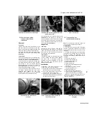
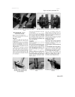
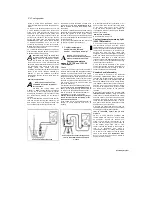
30.4b Thread a suitable bolt into the plug and 

pull it out


rod  as  a  guide  to  align  the  holes,  as  once  the 
retainer is in the housing it will be difficult to turn. 
Use  a  hammer  and  block  of  wood  to  drive  the 
shaft  fully  home 

(see  illustration). 

Apply  a 

suitable 

non-permanent 

thread 

locking 

compound to the Torx screws and tighten them to 
the  torque  setting  specified  at  the  beginning  of 
the  Chapter. 

Note: 

It  is  advisable  to  renew  the 

Torx  screws  because  the  originals  are  likely  to 
have been damaged by previous staking. 

Using a 

suitable  punch,  stake  the  screws  against  the 
retainer 

(see  illustration). 

If  it  was  removed,  fit 

the  blanking  plug  with a  new  O-ring and  press  it 
home 

(see illustrations).


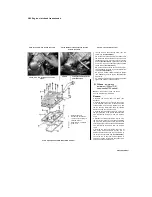
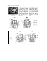
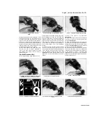
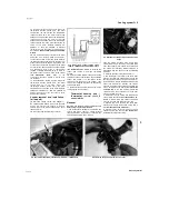
30.7a Note how the holes must align 

(arrow)


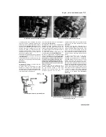
30.7c Install the Torx screws (arrowed) and 

stake them in place


Staned by Stalker


%


I


^


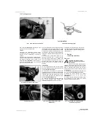
30.7b Tap the shaft into place as shown


Summary of Contents for XTZ750

Page 1: ...iances in damp conditions and again beware of creating a spark or applying excessive heat in the vicinity of fuel or fuel vapour Also ensure that the appliances meet national safety standards A severe electric shock can result from touching certain parts of the electrical system such as the spark plug wires HT leads when the engine is running or being cranked particularly if components are damp or...

Page 2: ...found all the identification numbers record them for reference when buying parts Since the manufacturers change specifications parts and vendors companies that manufacture various components on the machine providing the ID numbers is the only way to be reasonably sure that you are buying the correct parts Whenever possible take the worn part to the dealer so direct comparison with the new componen...

Page 3: ...r e a k e r s y ard for direct comparison Whether buying new used or rebuilt parts the best course is to deal directly with someone who specialises in parts for your particular make Started by Stalker UNREGISTERED VERSION OF PICTURE DESK ...

Page 4: ...chemical oil additives or oils with a grade of SH CD or higher or oils labelled ENERGY CONSERVING II Such additives or oils could cause clutch slip Oil type API grade SE SF or SG Oil viscosity SAE10W30or10W40 Bike care If you have to add oil frequently you should check whether you have any oil leaks If there is no sign of oil leakage from the joints and gaskets the engine could be burning oil see ...

Page 5: ...ycle held vertical the oil level should lie between the upper and lower level lines marked on the oil tank arrowed r If the level is below the lower line remove the filler cap arrowed from the top of the oil tank 10 Top the tank up with the recommended grade and type of oil to bring the level up to the upper line on the window Scaned by Stalker ...

Page 6: ...ion of an hydraulic leak somewhere in the system which should be investigated immediately Check for signs of fluid leakage from the hydraulic hoses and components if found rectify immediately Check the operation of both brakes before taking the machine on the road if there is evidence of air in the system spongy feel to lever or pedal it must be bled as described in Chapter 7 Front brake fluid lev...

Page 7: ...dy it must be above LOWER level line arrowed f If topping up is required on TDM models remove the seat and J on TRX models remove the side covers see Chapter 8 On TRX and XTZ models remove the cap clamp then on TRX models support the reservoir or refit the screw Unscrew the reservoir cap arrowed and remove the plate and diaphragm 4 Top up with new clean hydraulic fluid of the recommended 4 O I typ...

Page 8: ...ne at any time the surplus should be siphoned or drained off to prevent the possibility of it being expelled out of the breather hose If the coolant level falls steadily check the system for leaks see Chapter 1 If no leaks are found and the level continues to fall it is recommended that the machine is taken to a Yamaha dealer for a pressure test On TDM models the coolant reservoir FULL and LOW lev...

Page 9: ...odels Rider only Rider and passenger or high speed 28 psi 2 0 Bar 28 psi 2 0 Bar 33 psi 2 25 Bar 36 psi 2 50 Bar 1996 on TDM models All loads speeds 40 psi 2 75 Bar 33 psi 2 25 Bar TRX models Rider only Rider and passenger or high speed 33 psi 2 25 Bar 36 psi 2 50 Bar 36 psi 2 50 Bar 41 psi 2 80 Bar XTZ models Rider only Rider and passenger or high speed 33 psi 2 25 Bar 33 psi 2 25 Bar 33 psi 2 25...

Page 10: ...odels 23 Fuel system check 6 Headlight aim check and adjustment 30 Idle speed check and adjustment 3 Nuts and bolts tightness check 15 Sidestand check 14 Sidestand lever pivots and cables lubrication 18 Spark plugs gap check and adjustment 2 Steering head bearings freeplay check and adjustment 21 Steering head bearings lubrication 25 Suspension check 20 Swingarm and suspension bearings TDM and TRX...

Page 11: ...0 rpm 250 to 270 mm Hg 270 to 290 mm Hg 240 to 260 mm Hg carburettors 10 mm Hg 5 mm Hg 0 15 to 0 20 mm 0 25 to 0 30 mm 152 psi 10 5 Bar 158 psi 10 9 Bar 146 psi 10 1 Bar 14 5 psi 1 0 Bar 175 psi 12 0 Bar 182 psi 12 5 Bar 145 psi 10 0 Bar 14 5 psi 1 0 Bar 138 psi 9 5 Bar 144 psi 9 9 Bar 132 psi 9 1 Bar 14 5 psi 1 0 Bar Cycle parts Drive chain slack TDM models TRX models XTZ models Front brake lever...

Page 12: ...and all TRX models Oil change 3 5 litres Oil and filter change 3 6 litres Following engine overhaul dry engine new filter 4 2 litres Coolant type 50 distilled water 50 corrosion inhibited ethylene glycol anti freeze Note Yamaha specify that soft tap water can be used but NOT hard water If in doubt boil the water first or use only distilled water Coolant capacity Radiator and engine 1 7 litres Rese...

Page 13: ...ir 7 Drive chain adjuster 8 Idle speed adjuster 9 Oil drain plug Scaned by Stalker TDM 1 Rear brake fluid reservoir 2 Oil level window 1996 on 3 Oil filler cap 1996 on 4 Front brake fluid reservoir 5 Throttle cable upper adjuster 6 Radiator pressure cap 7 Coolant drain plug on water pump Clutch cable lower adjuster Oil filter and filter housing drain plug 10 Battery 1996 on ...

Page 14: ...ble upper adjuster 7 Radiator pressure cap 8 Coolant drain plug on water pump 9 Clutch cable lower adjuster 10 Oil filter and filter housing drain plug TRX 1 Clutch cable upper adjuster 2 Steering head bearing adjuster 3 Air filter 4 Idle speed adjuster 5 Battery 6 Drive chain adjuster 7 Oil drain plug Staned by Stalker UNREGISTERED VERSION OF PICTURE DESK ...

Page 15: ...4 Front brake fluid reservoir 5 Steering head bearing adjuster 6 Coolant drain plug on water pump 7 Clutch cable lower adjuster 8 Oil filter and filter housing drain plug Radiator pressure cap Clutch cable upper adjuster Air filter Battery Coolant reservoir Drive chain adjuster Oil drain plug Scaned by Stalker XTZ ...

Page 16: ...ads Section 8 Check the brake system and brake light switch operation Section 9 Check and adjust the clutch Section 10 Check the battery Section 11 D Check the condition of the wheels and tyres Section 12 Check the wheel bearings Section 13 Check the sidestand Section 14 Check the tightness of all nuts bolts and fasteners Section 15 Check the cooling system Section 16 Check and adjust the throttle...

Page 17: ...cifications see illustration As the chain stretches with wear adjustment will periodically be necessary see below Since the chain will rarely wear evenly roll the bike forwards so that another section of chain can be checked do this several times to check the entire length of chain and position the tightest spot midway between the sprockets on the bottom run of the chain 4 In some cases where lubr...

Page 18: ...hed tighten the nut to align it DO NOT loosen it Lubrication 14 If required wash the chain in paraffin l Hd On TDM and XTZ models check the relative position of the marker A and the notches B on each side kerosene then wipe it off and allow it to dry using compressed air if available If the chain is excessively dirty it should be removed from the machine and allowed to soak in the paraffin see Cha...

Page 19: ...k plugs by sandblasting is permitted provided you clean the plugs with a high flash point solvent afterwards 8 Before installing the plugs make sure they are the correct type and heat range and check the gap between the electrodes see illustrations Compare the gap to that specified and adjust as necessary If the gap must be adjusted bend the side electrode only and be very careful not to chip or c...

Page 20: ...m any kind of work on the fuel system wear safety glasses and have a fire extinguisher suitable for a Class B type fire flammable liquids on hand gauge take off points on the intake manifolds Do not allow exhaust gases to build up in the work area either perform the check outside or use an exhaust gas extraction system 1 Carburettor synchronisation is simply the process of adjusting the carburetto...

Page 21: ...spond to small changes in pressure 11 The vacuum readings for both cylinders should be the same If the vacuum readings differ proceed as follows 12 The carburettors are adjusted by turning the synchronising screw situated in between the carburettors in the throttle linkage see illustration Note Do not press down on the screw whilst adjusting it otherwise a false reading will be obtained When the c...

Page 22: ...if fuel starvation is suspected 5 On TRX XTZ and 1991 to 1998 TDM models the fuel filters are mounted in the tank On TDM models the filters are integral with the fuel outlet assembly from the tank On TRX and XTZ models the filters are integral with the fuel tap On XTZ models each fuel tap has its own filter Remove the tafc m mjrl 1 Wr A m 7 4b and allow the oil to drain 5 6 Make sure the element i...

Page 23: ...ent that the indicators contact the disc itself as the disc will be damaged 3 On XTZ models the indicators are in the form of grooves in the brake pad friction material when the pads are worn so that the grooves are only just visible the pads must be renewed see illustration 4 If the pads are worn to or beyond the indicators they must be renewed If the pads are dirty or if you are in doubt as to t...

Page 24: ...kwise If the brake light comes on too soon or is permanently on turn the ring anti clockwise If the switch doesn t operate the brake light check it see Chapter 9 9 5c Rear brake light switch XTZ models 6 On TDM and TRX models the front brake lever has a span adjuster which alters the distance of the lever from the handlebar see illustrations Each setting is identified by a number on the adjuster w...

Page 25: ...il the required amount of freeplay is obtained see illustration To increase freeplay turn the adjuster clockwise To reduce freeplay turn the adjuster anti clockwise Tighten the locking ring securely 5 On TRX XTZ and 1996 on TDM models if all the adjustment has been taken up at the lever reset the adjuster to give a large amount of freeplay then set the correct amount of freeplay using the adjuster...

Page 26: ...ing sound loose ones will produce a lower pitch and overtightened ones will be higher pitched A spoke wrench will be needed if any of the spokes require adjustment Unevenly tensioned spokes will promote rim misalignment check the wheel runout and alignment see Chapter 7 and seek the help of a wheel building expert if this is suspected Tyres 4 Check the tyre condition and tread depth thoroughly see...

Page 27: ...nd indicating there is still pressure in the system wait until it stops Now press down on the cap and continue turning the cap until it can be removed Check the condition of the coolant in the system If it is rust coloured or if accumulations of scale are visible drain flush and refill the system with new coolant See Section 27 Check the cap seal for cracks and other damage if in doubt about the p...

Page 28: ...d lever pivots and cables lubrication Pivot points 1 Since the controls cables and various other components of a motorcycle are exposed to the elements they should be lubricated periodically to ensure safe and trouble free operation 2 The footrests clutch and brake levers brake pedal gearshift lever linkage and sidestand pivots should be lubricated frequently In order for the lubricant to be appli...

Page 29: ... to compress see illustration Any freeplay felt in either check indicates worn bearings in the suspension linkage TRX and XTZ models or swingarm or worn shock absorber mountings The worn components must be renewed see Chapter 6 8 To make an accurate assessment of the swingarm bearings remove the rear wheel see Chapter 7 and the bolt securing the shock absorber TDM models or suspension linkage asse...

Page 30: ...eliminated 10 If the Yamaha tool is not available using either a C spanner a peg spanner or a drift located in one of the notches slacken the adjuster nut slightly until pressure is just released then tighten it until all freeplay is removed then tighten it a little more This pre loads the bearings Now slacken the nut then tighten it again setting it so that all freeplay is just removed yet the st...

Page 31: ...inning of the Chapter see illustration 22 16 20 Re check the bearing adjustment as described above and re adjust if necessary 21 Install the handlebars see Chapter 6 Every 8000 miles 12 000 km or 12 months Carry out all the items under the 4000 mile 6000 km check plus the following Warning Be careful when draining the oil as the exhaust pipes the engine and the oil itself can cause severe burns 1 ...

Page 32: ...ly Check with your local refuse disposal company disposal facility or environmental agency to see whether they will accept the used oil for recycling Don t pour used oil into drains or onto the ground see Haynes Hint and UK s safe oil disposal contact in Section 7 23 Fuel filter renewal 1999 f TDMmodels 1 The fuel filter should be renewed periodically To do so loosen the hose clamps and slide them...

Page 33: ... panel see Chapter 8 On 1991 to 1995 TDM models and XTZ models remove the engine bashplate see Chapter 8 On TRX models remove the security bolt holding the radiator cap see illustration 16 6a Remove the radiator pressure cap by turning it anti clockwise until it reaches a stop see illustrations 16 6b and c If you hear a hissing sound indicating there is still pressure in the system wait until it s...

Page 34: ...the specified mixture until it reaches the top of the filler neck Refit the cap then on TRX models fit the security bolt 17 Check the coolant level in the reservoir and top up if necessary 18 Check the system for leaks 19 Do not dispose of the old coolant by pouring it down the drain Instead pour it into a heavy plastic container cap it tightly and take it into an authorised disposal site or garag...

Page 35: ...s turn the engine anti clockwise 270 3 4 turn so that the camshaft lobes for the No 2 right hand cylinder are facing away from each other The No 2 cylinder is now at TDC on the compression stroke Measure the clearances of the No 2 cylinder valves using the method described in Step 6 8 When all clearances have been measured and charted identify whether the clearance on any valve falls outside that ...

Page 36: ...NSTALLED SHIM SIZE 12 0 125 130 13 5 14 0 14 5 15 0 15 5 16 0 16 5 17 0 17 5 18 0 18 5 19 0 19 5 20 0 20 5 21 0 21 5 22 0 22 5 23 0 23 5 24 0 0 00 0 04 12 0 12 5 13 0 13 5 14 0 14 5 15 0 15 5 16 0 16 5 17 0 17 5 18 0 18 5 19 0 19 5 20 0 20 5 21 0 21 5 0 05 0 09 12 0 12 5 13 0 13 5 14 0 14 5 15 0 15 5 16 0 16 5 17 0 17 5 18 0 18 5 19 0 19 5 20 0 20 5 21 0 21 5 22 0 0 10 0 14 12 0 12 5 13 0 13 5 14 ...

Page 37: ...ht may cause problems for oncoming traffic or provide poor unsafe illumination of the road ahead Before adjusting the headlight aim be sure to consult with local traffic laws and regulations for UK models refer to MOT Test Checks in the Reference section 1 The headlight beam can adjusted both 30 2 Vertical adjuster A horizontal adjuster B 1991 to 1995 TDM models and XTZ models horizontally and ver...

Page 38: ... bolt in the left hand side of the cylinder head there is no need to remove it see illustration 4 Start the engine and allow it to idle After a short while oil should begin to seep out from the oil gallery plug see illustration If no oil has appeared after one minute stop the engine immediately 5 If the oil does not appear after one minute either the pressure regulator is stuck open the oil pump i...

Page 39: ...g clear It is advisable to wear some form of eye and face protection when carrying out this operation 6 Hold a piece of thick card to act as a chute beneath the fork drain screw on one fork slider then remove the drain screw and allow the oil to drain Pump the fork to expel all of the oil Now do the same on the other fork leg 7 Slide the fork tube down into the slider and withdraw the spacer sprin...

Page 40: ...lief valve removal inspection and installation 22 Oil tank removal and installation 1996 on TDM and TRX models 21 Operations possible with the engine in the frame 2 Operations requiring engine removal 3 Pistons removal inspection and installation 14 Piston rings inspection and installation 15 Pick up coil assembly removal and installation see Chapter 5 Recommended running in procedure 34 Selector ...

Page 41: ...37 mm Service limit max 0 08 mm Head diameter 25 9 to 26 1 mm Face width 2 06 to 2 46 mm Seat width 0 9 to 1 1 mm Margin thickness 0 8 to 1 2 mm Exhaust valve Stem diameter Standard 5 460 to 5 475 mm Service limit min 5 43 mm Guide bore diameter Standard 5 500 to 5 512 mm Service limit max 5 55 mm Stem to guide clearance Standard 0 025 to 0 052 mm Service limit max 0 10 mm Head diameter 27 9 to 28...

Page 42: ...0 to 0 50 mm Service limit max 0 70 mm Piston ring to groove clearance Standard 0 03 to 0 07 mm Service limit max 0 12 mm 2 nd middle ring 1991 to 1995 TDM models Ring width 3 5 mm Ring thickness 1 0 mm Ring end gap installed Standard 0 30 to 0 45 mm Service limit max 0 70 mm Piston ring to groove clearance Standard 0 02 to 0 055 mm Service limit max 0 12 mm 1996 on TDM models and TRX models Ring ...

Page 43: ...ice limit max 0 15 mm Rotor end float 0 03 to 0 08 mm Connecting rods Big end side clearance Standard 0 160 to 0 272 mm Service limit max 0 5 mm Big end oil clearance Standard 0 026 to 0 050 mm Service limit max 0 09 mm Crankshaft and bearings Main bearing oil clearance Standard 0 020 to 0 038 mm Service limit max 0 1 mm Runout max 1991 to 1995 TDM models and all XTZ models 0 02 mm 1996 on TDM mod...

Page 44: ...ing bolt nut 75 Nm Upper front mounting bolts 55 Nm Engine bracket to engine bolts left hand side 30 Nm Engine bracket to frame bolt left hand side 55 Nm Engine bracket to engine bolt with collar right hand side 55 Nm Engine bracket to frame bolts right hand side 30 Nm XTZ models Swingarm pivot bolt nut 90 Nm Lower rear mounting bolt nut 58 Nm Upper rear mounting bolt nut 58 Nm Frame downtube bolt...

Page 45: ... assembly and relief valve The oil tank is mounted behind the engine on 1991 to 1995 TDM models and all XTZ models and on the engine behind the cylinders on later TDM models and all TRX models The oil pumps are gear driven off the crankshaft The crankshaft also drives two balancer shafts which eliminate the vibration inherent in parallel twin engines The alternator and starter clutch are on the le...

Page 46: ...e to a suitable working height on an hydraulic ramp or a suitable platform Make sure the motorcycle is secure and will not topple over see Tools and Workshop Tips in the Reference section When disconnecting any wiring cables and hoses it is advisable to mark or tag them as a reminder to where they connect 2 If the engine is dirty particularly around its mountings wash it thoroughly before starting...

Page 47: ...f J 5 19b Slacken the clamp screw arrowed and detach the hose see illustration Discard the O ring as anew one must be used 20 At this point position an hydraulic or mechanical jack under the engine with a block of wood between the jack head and crankcase see illustration Make sure the jack is centrally positioned so the engine will not topple in any direction when the last mounting bolt is removed...

Page 48: ...the underside of the engine at the back and remove the brackets see illustrations 22 On TRX models unscrew the bolts securing the engine bracket to the frame and the engine on each side and remove the brackets along with the collar fitted with the right hand bracket see illustrations Note which bolt fits where as they are of different lengths Remove the caps from the upper front mounting bolts the...

Page 49: ...nting bolts not forgetting the washers with the upper and lower rear bolts they locate under the bolt head not the nut and the collar between the right hand engine bracket and the engine and tighten them finger tight Now tighten the lower rear mounting bolt nut first then the upper rear mounting bolt nut then the upper front mounting bolts left hand side first then the engine bracket to engine and...

Page 50: ...coolant see Chapter 1 2 On TDM and TRX models remove the thermostat housing see Chapter 3 When removing the housing remove it along with the pipe that bolts onto the valve cover rather than separating the hose from the pipe The pipe is secured by a bolt make sure the pipe O ring does not fall into the engine when easing out the pipe see illustration Discard the O ring as a new one must be used 3 O...

Page 51: ... an anti clockwise direction only see illustration Alternatively place the motorcycle on an auxiliary stand so that the rear wheel is off the ground select a high gear and rotate the rear wheel by hand in its normal direction of rotation 3 Turn the engine until the T mark on the rotor aligns with the static timing mark on the alternator cover a notch in the timing inspection hole and the camshaft ...

Page 52: ...ver or bar through the hole in the centre of the camshaft see illustration 8 29a or by counter holding the alternator rotor 6 Remove the cam chain tensioner see Section 9 7 Make a mark on each sprocket to denote whether it fits with the exhaust or inlet camshaft the appropriate existing letter can be highlighted Remove the sprocket bolts then draw each sprocket off the end of its camshaft and slip...

Page 53: ...ed into ten compartments and label each compartment 8 12a Check the lobes of the camshaft for wear here s an example of damage requiring camshaft repair or renewal with the location of its corresponding valve in the cylinder head and whether it belongs with an inlet or an exhaust valve If a container is not available use labelled plastic bags Using a pair of pliers or a magnet if necessary lift ea...

Page 54: ... and are not binding on the dowels While doing this don t let the camshafts rotate 16 Now unscrew the bolts a evenly and a little at a time in a criss cross pattern and carefully lift off the camshaft holders 17 To determine the oil clearance compare the crushed Plastigauge at its widest point on each journal to the scale printed on the Plastigauge container see illustration Compare the results to...

Page 55: ...sulphide oil a 50 50 mixture of molybdenum disulphide grease and engine oil to each of them Also apply it to the camshaft lobes 25 Verify that the T mark on the timing rotor is still aligned with the notch see Step 3 see illustration 8 3a Lay the inlet camshaft with six lobes onto the back of the head making sure the No 1 left hand cylinder lobes are facing backwards and the punch mark on the spro...

Page 56: ...With everything correctly aligned tighten the sprocket bolts to the torque setting specified at the beginning of the Chapter using a screwdriver or bar inserted through the hole in each camshaft to prevent them turning or by counter holding the alternator rotor see illustrations 30 Install the cam chain top guide and tighten the bolts to the same torque setting as the other camshaft holder bolts s...

Page 57: ...0 Cylinder head fb removal and installation gs Caution The engine must be completely cool before beginning this procedure or the cylinder head may become warped Note 1 The cylinder head can be removed with the engine in the frame If the engine has been removed ignore the steps which don t apply Note 2 If no work is being carried out on the valves the cylinder head can be removed with the camshafts...

Page 58: ... careful not to let any of the gasket material fall into the crankcase the cylinder bores or the oil passages IJTHJT33 Refer to Tools and milUSi workshop Tips in the HiWT 12 If removed install the dowels into the cylinder block see illustration 10 13 Lubricate the cylinder bores with engine oil 13 Ensure both cylinder head and block mating surfaces are clean then lay the new head gasket in place o...

Page 59: ...the risk of damaging them a valve spring compressor is absolutely essential Make sure that it is suitable for motorcycle work Disassembly 3 Before proceeding arrange to label and store the valves along with their related components in such a way that they can be returned to their original locations without getting mixed up see illustration A good way to do this is to use the same container as the ...

Page 60: ...use Prussian blue to determine the extent of valve seat wear Uniformly coat the seat with the Prussian blue then install the valve and rotate it back and forth using a lapping tool Remove the valve and check whether the ring of blue on the valve is uniform and continuous around the valve and of the correct width as specified 14 Measure the valve stem diameter see illustration Clean the valve guide...

Page 61: ...the valve 21 Apply a small amount of coarse grinding compound to the valve face then slip the valve into the guide see illustration Note Make sure each valve is installed in its correct guide and be careful not to get any grinding compound on the valve stem 22 Attach the grinding tool or hose to the valve and rotate the tool between the palms of your hands Use a back and forth motion as though rub...

Page 62: ...he spring retainer with its shouldered side facing down so that it fits into the top of the spring see illustrations 27 Apply a small amount of grease to the collets to help hold them in place as the pressure is released from the springs see illustration Compress the springs with the valve spring compressor and install the collets see illustration When compressing the spring depress them only as f...

Page 63: ...d and honed by a Yamaha dealer or engineer If the cylinders are rebored they will require oversize pistons and rings 8 If the precision measuring tools are not available take the block and pistons to a Yamaha dealer or engineer for assessment and advice 9 If the block and cylinders are in good condition and the piston to bore clearance is within specifications see Section 14 the cylinders should b...

Page 64: ... use force if the block appears to be stuck as the pistons and or rings will be damaged If clamps are used remove them once the pistons are in the bore 19 When the pistons are correctly installed in the cylinders press the block down onto the base gasket making sure it locates correctly onto the dowels 20 Fit a new O ring into the groove in the coolant union face and around the pipe joint see illu...

Page 65: ...ery careful to remove only the carbon deposits Do not remove any metal and do not nick or gouge the sides of the ring grooves 8 Once the deposits have been removed clean the pistons with solvent and dry them thoroughly If the identification previously marked on the piston is cleaned off be sure to re mark it with the correct identity Make sure the oil return holes below the oil ring groove are cle...

Page 66: ...me piston and cylinder during the end gap measurement procedure and engine assembly 3 To measure the installed ring end gap insert the top ring into the top of the first cylinder and square it up with the cylinder walls by pushing it in with the top of the piston The ring should be about 20 mm below the top edge of the cylinder To measure the end gap slip a feeler gauge between the ends of the rin...

Page 67: ...ch side of it The oil ring must be installed by hand 16 Clutch removal inspection lfe and installation Note The clutch can be removed with the engine in the frame If the engine has been removed ignore the steps which don t apply Removal 1 Drain the engine oil see Chapter 1 2 Detach the clutch cable from the operating lever on the clutch cover see Section 17 3 Working evenly in a criss cross patter...

Page 68: ...nti judder assembly can be left intact unless the clutch has been chattering juddering excessively If it is necessary to remove it remove the wire retainer ring plain plate anti judder spring and spring seat Inspection 13 After an extended period of service the clutch friction plates will wear and promote clutch slip Measure the thickness of each friction plate using a vernier caliper see illustra...

Page 69: ...ength of each clutch spring using a vernier caliper see illustration If any spring is below the service limit specified renew all the springs as a set 16 Inspect the clutch assembly for burrs and 1 E clip 2 Washer 3 Operating lever 4 Operating shaft 5 Return spring 6 Oil seal 7 Bearings 8 Pinion 9 Bolts 1 0 Springs 1 1 Pressure plate 1 2 Washer 1 3 Thrust bearing 1 4 Pullrod 7 5 Friction plates 7 ...

Page 70: ...8 Check the pressure plate thrust bearing and plate washer for signs of roughness wear or damage and renew any parts as necessary 19 On 1989 XTZ models if removed check the clutch centre anti judder assembly components consisting of the wire retainer ring plain plate anti judder spring and spring seat for wear or damage and renew any parts as necessary 20 Check the clutch operating mechanism in th...

Page 71: ...centre rotates freely after tightening Bend up the tabs of the lockwasher to secure the nut see illustration 27 On 1991 to 1995 TDM models and 1990 on XTZ models fit the inner plain plate 16 26e Bend up the lockwasher tabs to secure the nut on the clutch centre if it has become muddled with the rest it is distinguishable by its slick surface see illustration 28 Build up the clutch plates starting ...

Page 72: ...lign the shaft so that the operating lever is facing back but angled out slightly 32 Insert the dowels in the crankcase then set the pullrod so that its teeth point towards the rear Install the clutch cover using a new 16 30b then fit the springs washers and bolts and tighten them as described gasket and tighten its bolts evenly in a crisscross sequence to the specified torque setting see illustra...

Page 73: ...chanism lever noting how it fits see illustrations 17 1c and d 3 On all models fully slacken the lockring on the adjuster at the handlebar end of the cable then screw the adjuster fully in see illustration This resets it to the beginning of its adjustment span 4 Align the slots in the adjuster and lockwheel 17 1c Bend back the retaining tab with that in the lever bracket then pull the outer cable ...

Page 74: ...he starter clutch should be renewed 5 Examine the teeth of the starter idle reduction gear and the corresponding teeth of the starter driven gear and starter motor shaft Renew the gears and or starter motor if worn or chipped teeth are discovered 6 To renew the starter clutch sprag assembly hold the alternator rotor in a rotor holder then undo the three bolts securing the clutch to the rotor Remov...

Page 75: ...arm for cracks distortion and wear of its pawls and check for any corresponding wear on the selector pins in the selector drum Also check the stopper arm roller and the detents in the selector drum for any wear or damage and make sure the roller turns freely Renew any components that are worn or damaged 8 Inspect the shaft centralising spring see illustration and the stopper arm return spring for ...

Page 76: ...rough the case until the splined end comes out the other side see illustration 19 5 Locate the selector arm pawls onto the pins on the selector drum Make sure the centralising spring ends locate correctly on each side of the locating pin see illustration 13 Slide the washer onto the left hand end of the shaft then fit the E clip into its groove making sure it is secure see illustrations 19 4b and ...

Page 77: ... the scavenge pump and remove it if it is loose Inspection 7 If required the pumps can be disassembled for cleaning Remove the single assembly screw and separate the pump housing on the feed pump noting how the cam chain guide fits see illustrations Remove the housing locating pins if they are loose Draw the inner rotor with the 20 7c Draw out the shaft and remove the rotors driveshaft out of the ...

Page 78: ...them if necessary Damage to the steel drive gear is unlikely but if found will necessitate crankshaft renewal 14 If the pump is good make sure all the components are clean then lubricate them with new engine oil Assemble the housing making sure the pins locate correctly and tighten the assembly screw to the torque setting specified at the beginning of the Chapter not forgetting the cam chain guide...

Page 79: ...DM models andallTRXmodels Note To remove the oil tank the engine must be removed from the frame Removal 1 Remove the engine from the frame see Section 5 2 Unscrew the banjo bolts securing the oil pipe to the left hand side of the oil tank and to the cylinder head and the pipe bracket bolt and remove the pipe Discard the banjo bolt sealing washers as new ones must be used 3 Unscrew the two bolts se...

Page 80: ...ter 4 2 Drain the engine oil and remove the oil filter see Chapter 1 3 Unscrew the sump bolts slackening them evenly in a criss cross sequence to prevent distortion and remove the sump see illustration Discard the gasket as a new one must be used Note the positions of the dowels and remove them if they are loose 4 Remove the screws securing the oil strainer cover and remove the cover and the strai...

Page 81: ...pection and installation Note On 1991 to 1995 TDM models and XTZ models the balancer shafts can be removed with the engine in the frame If the engine has been removed ignore the steps which do not apply On 1996 on TDM models and all TRX models the engine must be removed from the frame Removal 1 On 1991 to 1995 TDM models and XTZ models remove the seat side covers and engine bashplate see Chapter 8...

Page 82: ...worth checking with a Yamaha dealer or bearing specialist 10 Check the shafts are straight by rolling them on a flat surface such as a piece of glass Also check the bearing surfaces for scuffing and wear Installation 11 Turn the crankshaft until the Woodruff key slot for the alternator rotor on the left hand end aligns with the triangular mark on the crankcase see illustration The best way to turn...

Page 83: ...ustration 15 Fit a new O ring around the oil passage collar see illustration 23 5b then fit the oil strainer holder see illustration Apply a suitable non permanent thread locking compound to the holder bolts and tighten them to the specified torque setting 16 On 1991 to 1995 TDM models and XTZ models if removed install the crankcase top cover dowels Fit the cover using a new gasket then tighten th...

Page 84: ...s as a set if necessary see Chapter 8 Chain guides 7 Check the guides for excessive wear deep grooves cracking and other obvious damage and renew them if necessary Check the condition of the pivot hardware on the rear guide and renew any components that are damaged or deteriorated Installation 8 Installation of the chain and guides is the reverse of removal noting the following a Apply engine oil ...

Page 85: ...nscrew the 6 mm lower crankcase bolts the 8 mm bolts and the 10 mm bolts see illustrations 25 4a and b Unscrew the bolts evenly a little at a time in a reverse of the numerical sequence until they are finger tight then remove them The number of each bolt is cast into the crankcase Note the copper washers fitted with some of the bolts and also the cable guide Note As each bolt is removed store it i...

Page 86: ...ond 1215 to the outer mating surface of one crankcase half see illustration Caution Do not apply an excessive amount of sealant as it will ooze out when the case halves are assembled and may obstruct oil passages Do not apply the sealant on or too close within 2 to 3 mm to any of the bearing inserts or surfaces 15 Check again that all components are in position particularly that the bearing shells...

Page 87: ...llars using new O rings 27 Main and connecting rod bearings general information 1 Even though main and connecting rod bearings are generally renewed during the engine overhaul the old bearings should be retained for close examination as they may reveal valuable information about the condition of the engine 2 Bearing failure occurs mainly because of lack of lubrication the presence of dirt or other...

Page 88: ...d check for any freeplay between the two see illustration Measure the pin external and compare the result to the specifications at the beginning of the Chapter see illustration If the piston pin is worn below the service limit it should be renewed 7 Refer to Section 27 and examine the connecting rod bearing shells If they are scored badly scuffed or appear to have seized new shells must be install...

Page 89: ...s The left hand number is for the left hand No 1 cylinder journal The connecting rod numbers are marked in ink on the flat face of the connecting rod and cap see illustration 22 A range of bearing shells is available To select the correct bearing for a particular connecting rod subtract the big end bearing journal number stamped on the crank web from the connecting rod number marked on the rod Com...

Page 90: ...e runout exceeds the limit the crankshaft must be renewed Oil clearance check 9 Whether new bearing shells are being fitted or the original ones are being re used the main bearing oil clearance should be checked before the engine is reassembled Main 29 4 To remove a main bearing shell push it sideways and lift it out bearing oil clearance is measured with a product known as Plastigauge 10 Clean th...

Page 91: ...arance falls into the specified range new bearing shells are not required provided they are in good condition If the clearance is beyond the service limit refer to the marks on the case and the marks on the crankshaft and select new bearing shells see Steps 24 and 25 Install the new shells and check the oil clearance once again the new shells may bring bearing clearance within the specified range ...

Page 92: ...ulling on the bolt see illustration Discard the plug O Ting as a new one must be used Once the plug is removed tap on the end of the shaft using a soft faced mallet to free it from the crankcase 5 If necessary the input shaft and output shaft can be disassembled and inspected for wear or damage see Section 31 6 Referring to Tools and Workshop Tips Section 5 in the Reference Section check the beari...

Page 93: ...er direction 2 Remove the 2nd gear pinion from the left hand end of the shaft using a puller referring to Tools and Workshop Tips Section 5 in the Reference Section if required see illustration If a legged puller is being used it will be easier to set it up with the legs behind the 5th gear pinion and draw the 2nd and 5th pinions off together Note In our experience an hydraulic press was needed to...

Page 94: ... If removed drive or press the 4th gear pinion bush onto the shaft aligning the oil hole in the bush with the hole in the shaft Slide the 4th gear pinion with the pinion dog holes facing away from the integral 1st gear onto the bush see illustration Slide the splined washer onto the shaft then fit the circlip making sure that it locates 31 15c and secure them with the circlip correctly in the groo...

Page 95: ...y engine oil to the mating surfaces of the shaft pinions and bushes When installing the circlips do not expand their ends any further than is necessary Install the stamped circlips so that their chamfered side faces the pinion it secures and the sharp edged sides faces the direction of thrust load see correct fitting of a stamped circlip illustration in Tools and Workshop Tips in the Reference sec...

Page 96: ...e 3rd gear pinion followed by the 1st gear pinion and the thrust washer see illustrations 41 Fit the caged ball bearing onto the right hand end of the shaft see illustration 42 Check that all components have been correctly installed 32 Selector drum and forks removal inspection and installation 1 3c Note To remove the selector drum and forks the engine must be removed from the frame and the crankc...

Page 97: ...amaged 9 The selector fork shaft can be checked for trueness by rolling it along a flat surface A bent shaft will cause difficulty in selecting gears and make the gearchange action heavy Renew the shaft if it is bent 10 Inspect the selector drum grooves and selector fork guide pins for signs of wear or damage If either component shows signs of wear or damage the selector s and drum must be renewed...

Page 98: ...er use of the transmission and a restraining hand on the throttle until at least 600 miles 1000 km have been covered There s no point in keeping to any set speed limit the main idea is to keep from labouring the engine and to gradually increase performance up to the 600 mile 1000 km mark These recommendations can be lessened to an extent when only a new crankshaft is installed Experience is the be...

Page 99: ...tent J Difficult suitable for experienced DIY 5j mechanic Very difficult suitable for expert DIY or professional S Specifications Coolant Mixture type and capacity see Chapter 1 Radiator Cap valve opening pressure 11 to 15 psi 0 75 to 1 05 Bar Fan switch Cooling fan cut in temperature 102 to 108 C Cooling fan cut out temperature 98 C Coolant temperature sensor Resistance 1991 to 1995 TDM models an...

Page 100: ...e off any spills immediately with plenty of water Antifreeze is highly toxic if ingested Never leave antifreeze tying around in an open container or in puddles on the floor children and pets are attracted by its sweet smell and may drink it Check with the local authorities about disposing of used antifreeze Many communities will have collection centres which will see that antifreeze is disposed of...

Page 101: ...his procedure 4 Remove the radiator see Section 7 5 Unscrew the three bolts securing the fan shroud and fan assembly to the radiator see illustration On TDM and TRX models unscrew the bolts on the front of the fan securing it to the shroud and remove the shroud Separate the fan blade from the motor and renew the motor On XTZ models individual components are not available and the entire fan assembl...

Page 102: ...turn the ignition switch ON see illustrations 4 9a b and c The temperature gauge needle should be on the C on the gauge Now earth the sender wire on the engine The needle should swing immediately over to the H on the gauge Caution Do not earth the wire for any longer than is necessary to take the reading or the gauge may be damaged If the needle moves as described above the sender is proven defect...

Page 103: ...crew the sender and remove it from the thermostat housing 16 Apply a suitable thread locking and sealing compound to the sender threads then install the sender and tighten it to the torque setting specified at the beginning of the Chapter Take care not to overtighten the sender as the housing could be damaged 17 Reconnect the sender wiring and top up the cooling system see Chapter 1 Thermostat hou...

Page 104: ...s at the top see illustration 6 6b 11 Fit a new O ring onto the cover using a dab of grease to keep it in place if required see illustration Fit the cover onto the housing then install the two bolts and tighten them to the torque setting specified at the beginning of the Chapter see illustrations 6 6a 12 Install the thermostat housing and tighten the bolt to the specified torque setting see illust...

Page 105: ...kage from the drainage hole remove the pump and renew it individual components except O rings and bolts are not available Removal 4 Drain the coolant see Chapter 1 Place a suitable container below the water pump to catch any residue as the water pump is removed On XTZ models remove the exhaust system see Chapter 4 Also unscrew the bolts securing the right hand frame downtube section and remove it ...

Page 106: ...rewdriver to slacken the larger bore hose clamps then slide them back along the hose and clear of the union spigot see illustrations 6 3 7 3a and b The smaller bore hoses are secured by spring clamps which can be expanded by squeezing their ears together with pliers see illustration 7 3c Caution The radiator unions are fragile Do not use excessive force when attempting to remove the hoses 3 If a h...

Page 107: ...Fuel tank and fuel tap s removal and installation 2 General information and precautions 1 Idle fuel air mixture adjustment general information 5 Idle speed check see Chapter 1 Throttle and choke cables check and adjustment see Chapter 1 Throttle cables removal and installation 11 Throttle position sensor 1996 on TDM models and all TRX models check and adjustment see Chapter 5 Easy suitable for nov...

Page 108: ...5 All other models 142 5 Main air jet 1991 to 1995 TDM models 50 1999 TDM models 65 All other models 60 Jet needle 1991 to 1995 TDM models 5G52 3 1996 to 1998 TDM models and all TRX models 5E185 2 5 1999 TDM models 1 6DJP17 2 6CL1 XTZ models 5C19 3 Needle jet 1991 to 1995 TDM models and all XTZ models Y 4 1996 to 1998 TDM models and all TRX models Y 2 1999 TDM models P 0 Pilot air jet XTZ models 6...

Page 109: ...lls cutters etc create sparks in the normal course of operation and must not be used near petrol gasoline or any component containing it Again remember the possible presence of fumes before using electrical equipment Always mop up any spilt fuel and safety dispose of the rag used Any stored fuel that is drained off during servicing work must be kept in sealed containers that are suitable for holdi...

Page 110: ...ed and secured by their clamps b Start the engine and check that there is no sign of fuel leakage then shut if off Fuel tank XTZ models Removal 14 Make sure the fuel filler cap is secure and both fuel taps are in the OFF position Remove the seat and the fairing side panels see Chapter 8 15 Release the clamp securing the fuel hose to each fuel tap and detach the hoses 16 Unscrew the bolts securing ...

Page 111: ...them as necessary if available If any of the components are worn or damaged beyond repair and are not available individually a new tap must be fitted On 1991 to 1998 TDM models note which hose fits where on the remote tap see illustration 27 Remove the screws securing the tap to the tank and withdraw the tap assembly see illustrations Check the condition of the O ring If it is in good condition it...

Page 112: ... necessary 4 3b Air filter housing bolt arrowed XTZ models 5 Idle fuel air mixture adjustment general information 1 Due to the increased emphasis on controlling exhaust emissions certain governmental regulations have been formulated which directly affect the carburation of this machine The pilot screws can be adjusted but the use of an exhaust gas analyser and an auxiliary tachometer capable of ac...

Page 113: ...carburettor cleaner a supply of clean rags some means of blowing out the carburettor passages and a clean place to work It is recommended that only one carburettor be overhauled at a time to avoid mixing up parts 7 4a Idle speed adjuster bolt arrowed TDM models 7 Carburettors removal and installation Warning Refer to the precautions given in Section 1 before starting work Removal 1 Remove the fuel...

Page 114: ... of removal noting the following a Check for cracks or splits in the cylinder head intake rubbers and renew them if necessary b Make sure the carburettors are fully engaged with the intake rubbers and the clamps are securely tightened c Make sure all hoses are correctly routed and secured and not trapped or kinked d Refer to Section 11 for installation of the throttle cables Check the operation of...

Page 115: ...rburettor body noting how it fits see illustration Remove the O ring and discard it as a new one must be used If required withdraw the float pivot pin and remove the float and needle valve then unhook the needle valve from the tab on the float noting how it fits see illustration 8 Unscrew and remove the starter jet then remove the main jet holder noting how it fits see illustration Remove the main...

Page 116: ...c IjS Difficult suitable for experienced DIY Q mechanic Very difficult suitable for expert DIY 2j or professional 2 Specifications General information Cylinder numbering Left 1 Right 2 Spark plugs see Chapter 1 Ignition timing At idle 10 BTDC Full advance 1991 to 1995 TDM models 42 BTDC 5000 rpm XTZ models 43 BTDC 6000 rpm 1996 on TDM models and TRX models not available Pick up coil Resistance 199...

Page 117: ...ilable any failure of the system can be traced to failure of a system component or a simple wiring fault Of the two possibilities the latter is by far the most likely In the event of failure check the system in a logical fashion as described below 2 Disconnect the HT leads from the spark plugs Connect each lead to a spare spark plug and lay each plug on the engine with the threads contacting the e...

Page 118: ...nce can be measured with a multimeter If the coil is undamaged and if the resistance readings are as specified at the beginning of the Chapter it is probably capable of proper operation although note that sometimes a fault is only evident when the coil is under load and the engine running at high speed 2 Remove the left hand side cover XTZ models or the seat all other models see Chapter 8 3 Discon...

Page 119: ...Make sure the wiring connectors and HT leads are securely connected Pick up coil check and replacement Check 1 On TDM and TRX models remove the seat and on XTZ models remove the left hand side cover see Chapter 8 Disconnect the battery negative ve lead 2 On TRX models remove the side covers see Chapter 8 3 Trace the pick up coil alternator wiring from the top of the alternator cover and disconnect...

Page 120: ...der is a I I mark The static timing mark with which this should align is the notch in the threads for the inspection plug on the alternator cover see illustration 6 Connect the timing light to the no 1 cylinder HT lead as described in the manufacturer s instructions JfJJJtM The timing marks can be highlighted with white paint HllUT to make them more visible under the stroboscope light 7 Start the ...

Page 121: ... of the sensor as described below 6 If the sensor is suspected of being faulty take it to a Yamaha dealer for further testing If it is confirmed to be faulty it must be renewed the sensor is a sealed unit and cannot therefore be repaired If the sensor is good have the ignitor checked by the dealer Adjustment 7 Before adjusting the sensor check the idle speed and carburettor synchronisation see Cha...

Page 122: ...head bearings lubrication see Chapter 1 Steering stem removal and installation 8 Suspension adjustments 12 Suspension check see Chapter 1 Swingarm inspection and bearing replacement 14 Swingarm removal and installation 13 Swingarm and suspension linkage bearings lubrication see Chapter 1 Easy suitable for novice with little experience fe Fairly easy suitable k for beginner with some experience gS ...

Page 123: ...ar holder clamp bolts XTZ models 20 Nm Handlebar retaining bolt TRX models 23 Nm Handlebar holder positioning bolt TRX models 10 Nm Handlebar holder clamp bolt TRX models 17 Nm Fork clamp bolts TDM and XTZ models 23 Nm TRX models Top yoke 23 Nm Bottom yoke 30 Nm Fork top bolt TDM models 24 Nm TRX and XTZ models 23 Nm Fork damper rod bolt TDM and TRX models 30 Nm Fork damper rod bolt XTZ models 62 ...

Page 124: ... noting how the return spring end locates in the bracket see illustration For easier access to the nut first unscrew the two bolts securing the bracket and remove it see illustration The footrest rubber can be renewed by removing the two screws that secure it to the footrest 2 On TRX models unscrew the nut from the back of the footrest bracket and separate the peg from the bracket The footrest rub...

Page 125: ...ide of the pedal shaft then remove the split pin from the clevis pin securing the master cylinder pushrod to the bracket see illustration Remove the clevis pin and separate the pushrod from the bracket then draw the shaft assembly out of the frame 10 On TRX models unhook the brake pedal return spring and the brake light switch spring from the bracket on the pedal Remove the split pin from the clev...

Page 126: ... auxiliary stand 2 On TDM and XTZ models unhook the stand springs then counter hold the pivot bolt and unscrew the nut on the inside of the bracket see illustration Withdraw the pivot bolt and remove the stand noting how it locates against the sidestand switch plunger 3 On TRX models unhook the stand springs then unscrew the retaining bolt see illustration Slide the stand off its pivot noting how ...

Page 127: ... cap from the holder positioning bolt then unscrew the bolt see illustration Slacken the handlebar holder clamp bolt then ease the handlebar holder up and off the fork Installation 8 Installation is the reverse of removal noting the following a On TDM models align the mark on the front of the handlebars with the mating surfaces of the holder see illustration Make sure the handlebars are centrally ...

Page 128: ...t or on TRX models to the collar and the contact areas between the lever and its bracket and to the clutch cable nipple Adjust the clutch cable freeplay see Chapter 1 Front brake lever 12 On XTZ models remove the hand guard see illustration 5 9 13 On TDM models remove the cap from the end of the master cylinder pushrod in the lever then remove the E clip the nut the spring and the plate see illust...

Page 129: ...orks up through the bottom yoke then install the wiring ties where appropriate onto the forks see illustration 6 6b Slide the forks up into the top yoke Check that the amount of protrusion of the fork tube above the top yoke is as noted on removal and equal on both sides On TDM and XTZ models the tops of the tubes should be flush with the top of the top yoke On TRX models the top of the fork tube ...

Page 130: ...ider see illustration 3 If the fork top bolt was not slackened with the fork in situ carefully clamp the fork tube in a vice equipped with soft jaws taking care not to overtighten or score its surface and slacken the top bolt 4 Unscrew the fork top bolt from the top of the fork tube see illustration The bolt can remain threaded on the pre load adjuster but remove it by holding the adjuster and uns...

Page 131: ...s against the damper rod seat Take care not to do this forcibly or the seat may be damaged Then pull the tube sharply outwards until the bottom bush strikes the top bush Repeat this operation until the top bush and seal are tapped out of the slider see illustration 13 With the tube removed slide off the oil seal washer and top bush noting which way up they fit see illustration Discard the oil seal...

Page 132: ...il seal washer with its flat side facing up see illustration Either use the Yamaha service tool or a suitable piece of tubing to tap the bush fully into place the tubing must be slightly larger in diameter than the fork tube and slightly smaller in diameter than the bush recess in the slider Take care not to scratch the fork tube during this operation it is best to make sure that the fork tube is ...

Page 133: ...ation Fit the spring seat with its shouldered side fitting down into the top of the spring see illustration 7 6 28 Fit a new O ring onto the fork top bolt Thread the pre load adjuster with the top bolt if it wasn t removed onto the damper rod as far as it will go then counter hold it and tighten the locknut securely against it see illustration and 7 5 If it was removed thread the top bolt onto the...

Page 134: ...hop 38 Invert the fork and withdraw the damper rod from inside the fork tube see illustration If required slide the rebound spring off the damper rod 39 Carefully prise out the dust seal from the top of the slider to gain access to the oil seal retaining clip see illustration 7 10 Discard the dust seal as a new one must be used 40 Carefully remove the retaining clip taking care not to scratch the ...

Page 135: ...ter 56 Clamp the slider upright in a soft jawed vice using the brake caliper mounting lugs taking care not to overtighten and damage them Pull the fork tube out of the slider as far as possible then install the spring and the spring seat On TRX models fit the spacer and the washer 57 Apply a smear of fork oil or grease to the new top bolt O ring Install the top bolt assembly making sure the bottom...

Page 136: ...Fork tube and bottom bush 7 59 Front fork components XTZ models 7 Damper rod and rebound spring 8 Damper rod seat 9 Dust seal 10 Retaining clip 11 Oil seal 12 Washer 13 Top bush 14 Slider 15 Oil drain screw and sealing washer 1989 94 models 16 Damper rod bolt and sealing washer UNREGISTERED VI Scaned by Stalker VERSION OF PICTURE D ...

Page 137: ...il the top bush and slide it down over the tube see illustration 7 22a Press the bush squarely into its recess in the slider as far as possible then install the oil seal washer see illustration 7 22b Either use the Yamaha service tool or a suitable piece of tubing to tap the bush fully into place the tubing must be slightly larger in diameter than the fork tube and slightly smaller in diameter tha...

Page 138: ...ervoir remains upright and so that no strain is placed on the hydraulic hoses 6 On TDM and TRX models remove the tabbed lockwasher noting how it fits then unscrew and remove the locknut using either a C spanner a peg spanner or a drift located in one of the notches see illustration Remove the washer 7 Supporting the bottom yoke unscrew the adjuster nut using either a C spanner a peg spanner or a d...

Page 139: ...t 9 Steering head bearings inspection and replacement Inspection 1 Remove the steering stem see Section 8 9 6 Drawbolt arrangement for fitting steering stem bearing outer races 1 Long bolt or threaded bar 2 Thick washer 3 Guide for lower race 2 Remove all traces of old grease from the bearings and races and check them for wear or damage 3 The outer races should be polished and free from indentatio...

Page 140: ...Place the machine on an auxiliary stand Position a support under the rear wheel so that it does not drop when the shock absorber is removed but also making sure that the weight of the machine is off the rear suspension so that the shock is not compressed 2 Remove the seat see Chapter 8 3 Unscrew the nut and withdraw the bolt 9 7b It is best to remove the lower bearing using a puller securing the b...

Page 141: ...nspect the damper rod for signs of bending pitting and oil leakage see illustration 13 Inspect the pivot hardware at the top and bottom of the shock for wear or damage and release the hose from its clip arrowed Installation 14 Installation is the reverse of removal Apply molybdenum disulphide grease to the shock absorber and linkage rod pivot points Install the bolts and nuts finger tight only unt...

Page 142: ...linkage arm noting which way round it fits Inspection 6 Withdraw the inner sleeves and lever out the grease seals from the linkage arm and swingarm noting their different sizes see Illustrations Thoroughly clean all 11 3a Shock absorber to linkage arm bolt A linkage rod to linkage arm bolt B linkage rod to swingarm bolt C linkage arm to frame bolt D TRX models 11 3b Shock absorber to linkage arm b...

Page 143: ...ls spring pre load is adjusted using a suitable spanner on the adjuster flats on the top of the forks see illustration The amount of pre load is indicated by lines on the adjuster There are five lines on TDM models and eight on TRX models The standard position is with the fifth 1991 to 1995 TDM models third 1996 on TDM models or sixth TRX models line just visible above the top bolt hex Turn the ad...

Page 144: ...pecified refer to Section 14 3 On TDM models unscrew the bolt which secures the caliper bracket to the swingarm and remove the bracket see Chapter 7 f Q r h rt J r Measurement A 12 10b and according to the specified settings Standard length A 5 4 mm Minimum length A 5 4 mm Maximum length A 15 4 mm Section 12 Step 2 Unscrew the bolts securing the hose guide to the swingarm noting how they also secu...

Page 145: ...2 Inspect all components for wear or damage as described in Section 14 Installation 13 If removed install the chain slider and tighten its bolt s securely see illustration 13 11 14 Remove the cap and washer where fitted from each side of the swingarm and withdraw the bearing spacer s see illustrations Lubricate the seals XTZ models and bearings with molybdenum disulphide grease TRX models or lithi...

Page 146: ...s closely looking for obvious signs of wear such as heavy scoring and cracks or distortion due to accident damage Any damaged or worn component must be renewed 3 Check the swingarm pivot bolt for straightness by rolling it on a flat surface such as a piece of plate glass first wipe off all old grease and remove any corrosion using fine emery cloth If the equipment is available place the axle in V ...

Page 147: ...thicknesses The shims should be fitted between the cap and washer if two shims are required fit one on each side whereas if only one shim is required fit this on the right hand side 11 Press the grease seals into their locations in each side of the swingarm bearing housings renewing them if they are damaged or deteriorated 12 Lubricate the bearings bushes and spacers with lithium based grease Do n...

Page 148: ...nvenient place to work on Obtain a new soft link never attempt to reuse an old link 14 Install the new soft link complete with an O ring on each of its pins through the chain ends from the inside of the chain Install an O ring over the pin ends and fit the side plate with its identification marks facing out use the chain tool to press the side plate into position 15 Stake the new link pins using t...

Page 149: ...ockwasher then fit the nut with its recessed side facing in and tighten it to the torque setting specified at the beginning of the Chapter using the method employed on removal to prevent the sprocket from turning see illustrations Bend up one of the pre formed tabs of the lockwasher against the nut flats see illustration 11 On TDM and XTZ models install the inner sprocket cover on TDM models not f...

Page 150: ... see illustration Note the spacer inside the coupling it should be a tight fit but remove it if it is likely to drop out Check the coupling for cracks or any obvious signs of damage Also check the sprocket studs for wear or damage 3 Lift the rubber damper segments from the wheel and check them for cracks hardening and general deterioration see illustration Renew the rubber dampers as a set if nece...

Page 151: ...spection and installation 13 Wheels alignment check 10 Wheels inspection and repair 9 Degrees of difficulty Easy suitable for k novice with little R expenence gjg Fairly easy suitable k for beginner with some experience Fairlydifficult k suitable for competent 5 DIY mechanic jS Difficult suitable for k experienced DTV 5j mechanic S VerydWficult k suitable for expert DIY J or professional jS Specif...

Page 152: ...ake master cylinder bolts TDM and TRX models 23 Nm XTZ models 20 Nm Brake caliper bleed valves 6 Nm Front wheel axle TDM models 58 Nm TRX models 65 Nm Front wheel axle clamp bolt TDM models 19Nm TRX models 20 Nm Front wheel axle nut XTZ models 110 Nm 1 General information TDM and TRX models are fitted with cast alloy wheels designed for tubeless tyres only XTZ models are fitted with spoked wheels ...

Page 153: ...remove the pad cover from the top of the caliper see illustration Remove the pad pin retaining clips then withdraw the pad pins from the caliper noting how they locate against the pad spring see illustrations Remove the spring noting how it fits then lift out the pads see illustrations Where fitted remove the shims from the back of the pads noting how they fit 2 On XTZ models slacken the pad retai...

Page 154: ...ully using a fine wire brush which is completely free of oil and grease to remove all traces of road dirt and corrosion Using a pointed instrument clean out the grooves in the friction material and dig out any embedded particles of foreign matter Any areas of giazing may be removed using emery cloth 5 Check the condition of the brake disc s see Section 4 6 Remove all traces of corrosion from the p...

Page 155: ...point to the outside of the caliper see illustration Apply the specified grease see Step 9 to the slider pins on the bracket and slide the bracket into the caliper see 1 A fcji 2 9c Apply the recommended lubricants to the pad friction areas inside the caliper and to the exposed portion of the caliper pistons A Duckhams Copper 10 B Shin Etsu G 40M or equivalent silicone grease 2 10 Clip the cover o...

Page 156: ... clean brake fluid only on the internal parts Brake cleaner or denatured alcohol can be used on external parts Removal 1 On XTZ models if removing the rear brake caliper unscrew the bolts securing the rear caliper shield and remove the shield see illustration If the brake pads are being removed from the calipers slacken the pad retaining pins now see illustration 2 2a 2 If the calipers are just be...

Page 157: ...eing used take great care not to damage the caliper bores 8 Remove and discard the piston seals in the same way 9 Clean the pistons and bores with clean brake fluid If compressed air is available use it to dry the parts thoroughly make sure it s filtered and unlubricated Caution Do not under any circumstances use a petroleum based solvent to clean brake parts 10 Inspect the caliper bores and pisto...

Page 158: ...y could become warped Set the wheel on wood blocks so the disc doesn t support the weight of the wheel 5 Mark the relationship of the disc to the wheel so it can be installed in the same position Unscrew the disc retaining bolts loosening them a little at a time in a criss cross pattern to avoid distorting the disc then remove the disc from the wheel see illustration Installation 6 Install the dis...

Page 159: ...to the bracket then release the clamp securing the reservoir hose to the union on the master cylinder see illustrations Remove the reservoir cap and lift off the diaphragm plate and the rubber diaphragm Drain the brake fluid from the reservoir into a suitable container then detach the reservoir hose from its union on the master cylinder Wipe any remaining fluid out of the reservoir with a clean ra...

Page 160: ...itch see Chapter 9 24 Attach the master cylinder to the handlebar and where marked fit the clamp with its UP mark facing up aligning the top mating surfaces of the clamp with the punch mark on the handlebar see illustration Tighten first the upper bolt then the lower bolt to the torque setting specified at the beginning of the Chapter see illustrations 5 8a and b 25 Connect the brake hose s to the...

Page 161: ...t town carefully and place the open end in a lean container The objective is to prevent wcessive loss of brake fluid fluid spills and lystem contamination 1 Remove the split pin and washer from the ilevis pin securing the brake pedal to the naster cylinder pushrod see illustration Vithdraw the clevis pin and separate the ledal from the pushrod Discard the split pin s a new one must be used Unscrew...

Page 162: ... the banjo bolt to the specified torque setting see illustrations 6 5a and b 24 Secure the fluid reservoir to the frame with its retaining bolt see illustrations 6 4a b and c Ensure that the hose is correctly routed then connect it to the union on the master cylinder and secure it with the clamp see illustration 6 5a and b Check that the hose is secure and clamped at the reservoir end as well If t...

Page 163: ...bing and the lever will move toward the handlebar or the pedal will move down 9 Retighten the bleed valve then release the brake lever or pedal gradually Repeat the process until no air bubbles are visible in the brake fluid leaving the caliper and the lever or pedal is firm when applied On completion disconnect the bleeding equipment then tighten the bleed valve to the torque setting specified at...

Page 164: ...rd and pull it tight so that it is roughly parallel to the floor Slowly bring the string into contact with the front sidewall of the rear tyre then turn the front wheel until it is parallel with the string Measure the distance from the front tyre sidewall to the string see illustration 6 Repeat the procedure on the other side of the motorcycle The distance from the front tyre sidewall to the strin...

Page 165: ...o rest on a disc the disc could become warped Set the wheel on wood blocks so the disc doesn t support the weight of the wheel or keep it upright 8 Check the axle for straightness by rolling it on a flat surface such as a piece of plate glass first wipe off all old grease and remove any corrosion using fine emery cloth If the axle is bent renew it 9 Check the condition of the wheel bearings see Se...

Page 166: ...he brake pedal with the calipers removed On TDM models slacken the caliper bracket bolt on the swingarm see illustration 3 Where fitted remove the split pin from the axle nut on the end of the axle see illustration Unscrew the axle nut and remove the washer and on TRX models the adjuster position marker see illustration 4 Support the wheel then withdraw the axle and lower the wheel to the ground s...

Page 167: ...disc 13 3b then lever out the retainer plate and remove the drive plate arrowed see Section 3 Tighten the caliper mounting bolts to the specified torque setting On XTZ models install the caliper shield see illustration 3 1 14 Operate the brake pedal several times to bring the pads into contact with the disc Check the operation of the rear brake carefully before riding the bike 13 Wheel bearings re...

Page 168: ...aring driver or a suitable socket to drive it into place if necessary see illustration 14 Clean off all grease from the brake discs using acetone or brake system cleaner then install the wheel see Section 11 Rear wheel bearings 15 Remove the rear wheel see Section 12 Lift the sprocket coupling out of the wheel noting how it fits see illustration 16 Set the wheel on blocks so as not to allow the we...

Page 169: ...o contact the outer race of the bearing drive it in until it is completely seated see illustration 13 10 30 Apply a smear of grease to the lips of the new seal and press it into the coupling using 13 26a Use a socket to drive out the spacer 13 26c Lever out the grease seal a seal or bearing driver a suitable socket or a flat piece of wood to drive it into place if necessary see illustration Instal...

Page 170: ... bead is substantial and is usually beyond the capabilities of an individual working with normal tyre levers Additionally the specialist will be able to balance the wheels after tyre fitting 5 Note that punctured tubeless tyres can in some cases be repaired Any such repairs must be carried out professionally by a motorcycle tyre fitting specialist and advice sought on reduced speed limits for repa...

Page 171: ...sistant will be required when removing panels to help avoid the risk of damage to paintwork Once the evident fasteners have been removed try to withdraw the panel as described but DO NOT FORCE IT if it will not release check that all fasteners have been removed and try again Where a panel engages another by means of tabs be careful not to break the tab or its mating slot or to damage the paintwork...

Page 172: ...ake sure the tabs at the front of the seat locate correctly under and on the back of the tank Push down on the rear of the seat to engage the latch TRX models 6 Insert the ignition key into the seat lock located below the side cover on the left hand side and turn it clockwise to unlock the passenger seat see illustration Remove the seat noting how it fits 7 Pull back the latch at the back of the r...

Page 173: ...lustration Carefully lift one side up to clear the frame then remove the assembly along with the tail light see illustration 3 Installation is the reverse of removal TRX models 4 Remove the seats see Section 2 5 Remove the six screws securing the side cover assembly see illustration Carefully lift one side up to clear the frame then remove the assembly see illustration 6 Installation is the revers...

Page 174: ...UNREGISTERED VI ScanedbyStalker UNREGISTERED VI ...

Page 175: ...quired remove the single screw securing the side trim panel and remove the panel noting how it locates onto the lug on the frame 5 Installation is the reverse of removal XTZ models 6 Remove the seven screws securing the side cover see illustration Carefully release the slot at the bottom from the tab then release the tabs at the top from the fairing and remove the panel see illustrations 7 Install...

Page 176: ...rectly and securely connected 1996 on TDM models Removal 4 Remove the fairing side panels see Section 4 Remove the three screws securing the instrument cluster cover and remove the cover and the foam damper see illustration 5 Remove the screws securing the windshield and remove the windshield Ease the rubber expanders out of the windshield mounting points in the fairing 5 4 Fairing mountings 1 Ins...

Page 177: ...w the nuts securing the rear view mirrors to the fairing bracket and remove the mirrors along with the rubber pads see illustrations 11 Disconnect the headlight auxiliary light and turn signal wiring connectors see illustrations 12 Remove the screw securing each side of the fairing and the four nuts securing the fairing and headlight to the bracket see illustration Carefully draw the fairing forwa...

Page 178: ...oval 1 On 1991 to 1995 TDM models unscrew the knurled ring securing the speedometer to the drive housing on the front wheel then detach 3 2b Mudguard mounting bolts arrowed TRX models 6 2c On are XTZ models the bolts arrowed on the inside of the fork leg Removal 1 On TDM models remove the cap from the end of the through bolt then remove the split pin and washer and withdraw the bolt see illustrati...

Page 179: ...eplacement 22 Starter circuit cut off relay check and replacement 25 Starter motor disassembly inspection and reassembly 29 Starter motor removal and installation 28 Starter relay check and replacement 27 Tail light assembly removal and installation 10 Turn signal bulbs renewal 12 Turn signal assemblies removal and installation 13 Turn signal circuit check 11 Degrees of difficulty Easy suitable fo...

Page 180: ... 7 5A Fan 7 5A XTZ models Main 30A Fan 10A Bulbs Headlight 1991 to 1995 TDM models 35 35W halogen x 2 1996 on TDM models 55W halogen H3 x 2 TRX models 60 55W halogen x 1 XTZ models 35 35W halogen x 2 Auxiliary light TDM models 5 0W x 1 TRX models 3 4W x 1 XTZ models 3 4W x 2 Brake tail light 21 5W Turn signal lights 21W Instrument and warning lights TRX XTZ and 1991 to 1998 TDM models Instrument l...

Page 181: ...ions or a blown fuse Prior to any electrical fault finding always visually check the condition of the fuse wires and connections in the problem circuit Intermittent failures can be especially frustrating since you can t always duplicate the failure when it s convenient to test In such situations a good practice is to clean all connections in the affected circuit whether or not they appear to be go...

Page 182: ...ttery negative ve terminal When fully charged there should be more than 12 5 volts present If the voltage falls below 12 5 volts the battery must be removed disconnecting the negative ve terminal first and recharged as described in Section 4 14 On XTZ models if available an hydrometer should be used to measure the specific gravity of the electrolyte Remove the battery and its cell caps then measur...

Page 183: ... this happens remove the corrosion with a wire brush or emery paper then spray the fuse end and terminals with electrical contact cleaner 6 Lighting system check 1 The battery provides power for operation of the headlight tail light brake light turn signals and instrument cluster lights If none of the lights operate always check battery voltage before proceeding Low battery voltage indicates eithe...

Page 184: ... to the headlight bulb s remove the fairing on TDM models and the relevant fairing side panel on XTZ models see Chapter 8 2 Disconnect the relevant wiring connector from the back of the headlight assembly and remove the rubber dust cover noting how it fits see illustrations 3 Release the bulb retaining ring or clip noting how it fits then remove the bulb see illustrations 4 Fit the new bulb bearin...

Page 185: ...t 8 3a Unscrew the nut on each side A and the central nut on the bottom B and auxiliary light Check the headlight aim see Chapter 1 9 Brake tail light bulb f renewal 1 On TDM models remove the seat see Chapter 8 On TRX models remove the passenger seat though best access is obtained by removing the side covers as well see Chapter 8 On XTZ models open the storage compartment cover behind the seat an...

Page 186: ...lash in the other direction Check the bulbs and the sockets see Section 12 3 The relay is mounted under the seat on TDM and TRX models and behind the fairing on XTZ models see illustrations Remove the seat or fairing for access see Chapter 8 If the bulbs and sockets are good check for voltage at the turn signal relay brown wire brown red on 1997 on UK models with the ignition ON If no voltage is p...

Page 187: ...older Do not overtighten the screw as the lens or threads could be damaged 13 Turn signal assemblies removal and installation k Removal 1 Disconnect the turn signal wiring connectors On the front turn signals they are on the inside of the fairing see illustrations On TDM models remove the fairing and on XTZ models the fairing side panel s for best access see Chapter 8 On the rear turn signals remo...

Page 188: ...le connector with the ignition ON connector halves remain joined If there s no voltage present check the wire between the switch and the ignition switch see the wiring diagrams at the end of this Chapter 4 If voltage is available touch the probe of the test light to the other terminal of the switch then pull the brake lever in or depress the brake pedal If no reading is obtained or the test light ...

Page 189: ...r Removal 1 Remove the fairing see Chapter 8 On TRX models remove the fuel tank and air filter housing for best access to the wiring connectors see Chapter 4 On XTZ models release the clips on the instrument cluster surround from the grommets on the cluster and remove the surround see illustration On TRX models remove the screws securing the trim cover to free the wiring loom see illustration 2 On...

Page 190: ...ents 16 Instruments check replacement and bulbs Speedometer Check TRX XTZ and 1991 to 1998 TDM models 1 Special instruments are required to properly check the operation of this meter If it is believed to be faulty take the motorcycle to a Yamaha dealer for assessment Check that the fault is not due to a broken cable Check 1999 TDM models 2 The electronic speedometer is supplied with wheel speed in...

Page 191: ...the cluster and lift off the front cover assembly see illustrations 16 6a b or c On 1999 TDM models remove the seven screws from the base of the cluster and separate the upper and lower covers from the instrument assembly note that the speedometer and tachometer are only available as a unit with their housing remove the fuel gauge and transfer it to the new assembly 13 Remove the screws securing t...

Page 192: ...ighest position and check the meter reading 4 to 10 ohms should now be indicated If the sender unit does not produce the correct readings it must be renewed 4 Before renewing the fuel gauge or the sender unit check that the fault is not due to a poor wire connection or break in any of the circuit wiring Check that the fuel level warning light bulb has not blown Replacement 5 Refer to Section 16 fo...

Page 193: ... 3 On TDM models remove the fairing see Chapter 8 On TRX models remove the air filter housing and on XTZ models remove the fuel tank see Chapter 4 Trace the wiring harness of the switch in question back to its connector and disconnect it see illustration and 18 1b and 15 3b 4 Check for continuity between the terminals of the switch harness with the switch in the various positions ie switch off no ...

Page 194: ... the wiring diagrams at the end of this Chapter Turn the ignition OFF Removal 6 Make sure the transmission is in neutral The switch is located in the left hand side of the transmission casing above the front sprocket To access the wiring connector on TDM models remove the seat on TRX models remove the side covers and on XTZ models remove the left hand side cover see Chapter 8 Trace the single ligh...

Page 195: ... Reconnect the wiring connector and check the operation of the sidestand switch 11 On TDM models install the seat on TRX models install the side covers and on XTZ models install the left hand side cover see Chapter 8 23 Clutch switch check and replacement Check 1 The clutch switch is mounted on the underside of the clutch lever bracket on TDM and TRX models and is a push fit into the bracket on th...

Page 196: ... starter circuit cut off relay is part of the safety circuit which prevents or stops the engine running if the transmission is in gear whilst the sidestand is down and prevents the engine from starting if the transmission is in gear unless the sidestand is up and the clutch lever is pulled in 2 If the starter circuit is faulty first check the fuse see Section 5 The starter cut off relay is located...

Page 197: ...r lead see illustration position the lead away from the relay terminal With the ignition switch ON the engine kill switch in the RUN position the transmission in 26 3c and mounting bolt B TRX models neutral and the clutch pulled in press the starter switch The relay should be heard to click 3 If the relay doesn t click switch off the ignition and remove the relay as described below test it as foll...

Page 198: ...tion Slide the starter motor out from the crankcase and remove it from the machine see illustration 5 Remove the O ring on the end of the starter motor and discard it as a new one must be used Installation 6 Install a new O ring on the end of the starter motor and ensure it is seated in its groove see illustration Apply a smear of engine oil to the O ring to aid installation 7 Manoeuvre the motor ...

Page 199: ...illustration 4 Wrap some insulating tape around the teeth on the end of the starter motor shaft this will protect the oil seal from damage as the front cover is removed Remove the front cover from the motor see illustration Remove the cover O ring from the main housing and discard it as a new one must be used Remove the shims from the front end of the armature shaft or the inside of the front cove...

Page 200: ...do not use sandpaper or emery paper After cleaning wipe away any residue with a cloth soaked in electrical system cleaner or denatured alcohol Measure the diameter of the commutator and compare It to the specifications If it has worn below the wear limit renew the starter motor Measure the depth of the insulating Mica below the surface of the commutator bars If the Mica is less than the depth spec...

Page 201: ...ut becoming entangled with the exposed brush ends 18 Insert the armature into the main housing noting that it will be forcibly drawn in by the attraction of the magnets see illustration 29 6 Remove the strips securing the brushes Check that each brush is securely pressed against the commutator Reassembly 15 Fit the brushplate seat into the main housing see illustration Ensure that the inner rubber...

Page 202: ...by testing of the individual components Note Before beginning the checks make sure the battery is fully charged and that all system connections are clean and tight 2 Checking the output of the charging system and the performance of the various components within the charging system requires the use of a multimeter with voltage current and resistance checking facilities 3 When making the checks foll...

Page 203: ...eft hand side of the engine and disconnect it at the white connector containing the three white wires see illustrations 3 Using a multimeter set to the ohms x 1 ohmmeter scale measure the resistance between each of the white wires on the alternator side of the connector taking a total of three readings then check for continuity between each terminal and earth If the stator coil windings are in goo...

Page 204: ... 9 Withdraw the shaft arrowed and remove the gear the position of the dowels and remove them if loose 9 Withdraw the shaft from the starter idle reduction gear and remove the gear noting how it fits see illustration 10 To remove the rotor bolt it is necessary to stop the rotor from turning If a rotor holding strap or tool is not available and if the engine is still in the fame place the transmissi...

Page 205: ...ligning the slot arrowed with the key idle reduction gear making sure it engages correctly with both the starter motor pinion and the starter clutch pinion and insert the shaft see illustration 32 9 17 Install the alternator cover using a new gasket making sure it locates onto the dowels and tighten the cover bolts evenly in a criss cross pattern to the specified torque setting see illustrations C...

Page 206: ...e fairing Remove the fairing for access see Chapter 8 On 1991 to 1995 33 3a Regulator rectifier 1991 to 1995 TDM models models remove the air filter housing for access to the wiring connector see Chapter 4 see illustration 4 On TRX models the regulator rectifier is mounted to the underside of the rear mudguard near the top of the shock absorber see illustration Remove the rider s seat to access it...

Page 207: ...Wiring diagrams 9 29 _____Scaned by Stalker 5 l 6o Cxj fi I JICM ...

Page 208: ...UNREGISTERED VI 9 30 Wiring diagrams UNREGISTERED VERSION 01 ONREGISTEREDVI Scaned by Stalker ONREGISTERED VERSION 0 ...

Page 209: ...I UNREGISTERED VI Wiring diagrams 9 31 ____ Scaned by Stalker UNREGISTERED VERSION OF PICTURE DESK ...

Page 210: ...9 32 Wiring diagrams Scaned by Stalker ...

Page 211: ...XTZ750 gauge Starter circuit Neutral Starter cut off relay switch rnotor ...

Reviews: