UNREGISTERED VI
Electrical system 9»19
Replacement
5
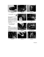
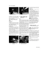
The starter cut-off relay is located under the
seat on all except 1996-on TDM models, where it
is behind the fairing. Remove the seat or fairing
for access (see Chapter 8). Disconnect the relay
wiring connector and remove the relay
(see
Illustrations 25.2a and b, and 11.3b).
6
Installation is the reverse of removal.
1. ..
,*
26 Horn
-
§&
check and replacement
||
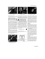
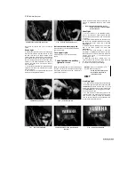
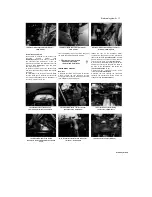
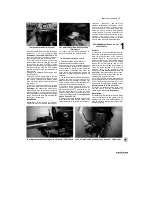
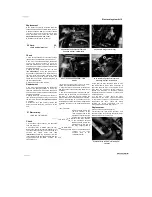
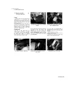
26.3a Horn wiring connectors (A) and
mounting bolt (B) - TDM models
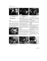
26.3b Horn wiring connectors (A).
Check
1 If the horn, doesn't work, first check the fuse
(see Section 5) and the battery (see Section 3).
2 The horn is mounted behind the fairing side
panels or the fairing, depending on model. On
TDM and TRX models, remove the fairing, and
on XTZ models remove the left-hand fairing side
panel (see Chapter 8).
3 Unplug the wiring connectors from the horn
(see Illustrations).
Using two jumper wires,
apply battery voltage directly to the terminals on
the horn. If the horn sounds, check the switch
(see Section 19) and the wiring between the
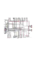
switch and the horn (see the
wiring diagrams
at
the end of this Chapter).
4 If the horn doesn't sound, renew it.
Replacement
5 The horn is mounted behind the fairing side
panels or the fairing, depending on model. On
TDM and TRX models, remove the fairing, and
on XTZ models remove the left-hand fairing side
panel (see Chapter 8).
6 Unplug the wiring connectors from the horn,
then unscrew the bolt(s) securing the horn and
remove it from the bike
(see Illustrations 26.3a,
b,
c and
d).
7 Install the horn and securely tighten the
bolt(s). Connect the wiring connectors to the
horn.
27 Starter relay -
check and vep\acemerA
,:■?
■■■-■' -■■■'■
::/:-
■ ■
Check
1 If the starter circuit is faulty, first check the
fuse (see Section 5).
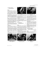
2 The starter relay is located under the seat.
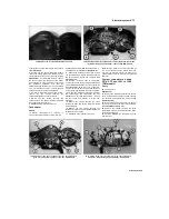
Remove the seat for access (see Chapter 8). Lift
the rubber terminal cover and unscrew the bolt
securing
the
starter
motor
lead
(see
illustration);
position the lead away from the
relay terminal. With the ignition switch ON, the
engine kill switch in the RUN position, the
transmission in
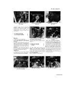
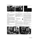
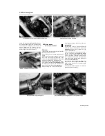
26.3c ... and mounting bolt (B) - TRX
models
neutral and the clutch pulled in, press the starter
switch. The relay should be heard to click.
3 If the relay doesn't click, switch off the ignition
and remove the relay as described below; test it
as follows.
4 This test is made with the relay removed from
the bike and on the bench. Set a multimeter to
the ohms x 1 scale and connect it across the
relay's starter motor and battery lead terminals.
Using a fully-charged 12 volt battery and two
insulated jumper wires, connect the jumper leads
as follows according to the model being worked
on:
1991 to 95 TDM
Battery positive lead to the
red wire terminal of the
relay, negative lead to the
blue/white terminal Battery
positive lead to the red/white
wire terminal of the relay, negative
lead to the blue/white terminal
Battery positive lead to the
blue/white wire terminal of
the relay, negative lead to
the red terminal
Battery positive lead to the blue/white wire
terminal
of
the
relay,
negative
lead
to
the
red/white terminal
26.3d Horn wiring connectors (A) and
mounting bolt (B) - XTZ models
At this point the relay should be heard to click
and the multimeter read 0 ohms (continuity). If
this is the case the relay is proved good. If the
relay does not click when battery voltage is
applied and indicates no continuity (infinite
resistance) across its terminals, it is faulty and
must be renewed.
5 If the relay is good, check the other
components in the starter circuit as described
in the relevant sections of this Chapter. If all
components are good, check the wiring
between the various components (see the
wiring diagrams
at the end of this book).
Replacement
6 Remove the seat (see Chapter 8).
7 Disconnect the relay wiring connector, and
unscrew the two nuts securing the starter motor
and battery leads to the relay and
UNREGISTERED VI
Scaned by Stalker
1996-on TDM
TRX
XTZ
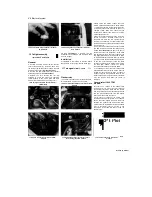
27.2 Detach the starter motor lead from
the relay

