3*4 Cooling system
cutting in at the wrong temperature, a more
comprehensive test of the switch can be made as
follows.
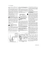
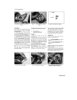
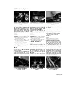
12 Remove the switch (see Steps 14 to 17). Fill
a small heatproof container with coolant and
place it on a stove. Connect the probes of an
ohmmeter to the terminals of the switch, and
using some wire or other support suspend the
switch in the coolant so that just the sensing
portion and switch body are submerged
(see
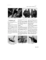
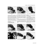
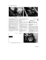
illustration).
Also place a thermometer capable
of reading temperatures up to 110*0 in the
coolant so that its bulb is close to the switch.
Note:
None of the components should be allowed
to directly touch the container.
13 Initially the ohmmeter reading should be very
high indicating that the switch is open (OFF).
Heat the coolant, stirring it gently.
Warning: This must be done very
carefully to avoid the risk of personal
injury.
When the temperature reaches
around 102 to 108°C the meter reading should
drop to around zero ohms, indicating that the
switch has closed (ON). Now turn the heat off. As
the temperature falls below 98°C the meter
reading
should
show
infinite
(very
high)
resistance, indicating that the switch has opened
(OFF). If the meter readings obtained are
different, or they are obtained at different
temperatures, then the switch is faulty and must
be renewed.
Removal and installation
Warning: The engine must be
completely cool before carrying out
this procedure.
14
Drain the cooling system (see
Chapter 1).
Note:
The fan switch is positioned
near the top of the cooling system so coolant
draining can be avoided if care is taken to catch
any coolant which escapes as the switch is
removed.
15
On TDM and TRX models, remove the fuel
tank and air filter housing (see Chapter 4). On
XTZ models, remove the left-hand fairing side
panel (see Chapter 8). Disconnect the wiring
connector(s) from the fan switch, mounted in the
thermostat housing
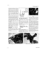
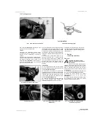
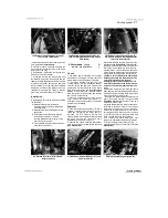
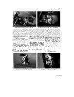
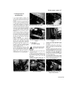
(see illustrations 4.9a, b
and c).
Unscrew the switch and withdraw it from
the housing.
16 Apply a suitable thread locking and sealing
compound to the switch threads, then install the
switch and tighten it to the torque setting
specified at the beginning of the Chapter. Take
care not to overtighten the switch as the housing
could be damaged.
17 Reconnect the switch wiring and refill or top
up the cooling system (see Chapter 1).
5 Coolant temperature
gauge/warning light and
sender - check and renewal ^
Warning: The engine must be
completely cool before carrying out
work on the temperature sender.
Coolant temperature
gauge (XTZ, TRX and 1991-98
TDM models)
Check
1 The circuit consists of the sender mounted in
the thermostat housing and the gauge assembly
mounted in the instrument panel. If the system
malfunctions check first that the battery is fully
charged and that the fuses are all good. If they
are, on TDM and TRX models, remove the fuel
tank and air filter housing (see Chapter 4). On
XTZ models, remove the left-hand fairing side
panel (see Chapter 8).
2 Disconnect the wire from the sender and turn
the ignition switch ON
(see illustrations 4.9a, b
and c).
The temperature gauge needle should be
on the C on the gauge. Now earth the sender
wire on the engine. The needle should swing
immediately over to the H on the gauge.
Caution: Do not earth the wire for any longer
than is necessary to take the reading, or the
gauge may be damaged.
If the needle moves as described above, the
sender is proven defective and must be
renewed.
3
If the needle movement is still faulty, or if it
does not move at all, the fault lies in the wiring
or the gauge itself. Check all the relevant
wiring and wiring connectors (see Chapter 9).
If all appears to be well, the gauge is defective
and must be renewed.
Removal and installation
4
See Chapter 9, Section 16.
Coolant temperature warning light
(1999 TDM models)
5 The circuit consists of the sender mounted in
the
thermostat
housing and
the
coolant
temperature warning light in the instrument panel.
The warning light should illuminate briefly when
the ignition is first turned on as a check of the
warning light bulb; the light should then
extinguish. If the bulb doesn't
light,
it is probably
blown and should be renewed as described in
Chapter 9.
Less
likely is a wiring fault, but
referring to the wiring diagram at the end of this
manual, check the coolant temperature warning
light circuit wiring for continuity.
6 The bulb should illuminate if the engine
coolant ever reaches too high a temperature. If
you suspect that the bulb is failing to come on
check the sender as described below.
Sender check (all models)
7 The sender is mounted in the thermostat
housing. On TDM and TRX models, remove the
fuel tank and air filter housing (see Chapter 4).
On XTZ models, remove the left-hand fairing side
panel (see Chapter 8). Drain the cooling system
(see Chapter 1).
Note:
The sender is positioned
near the top of the cooling system so coolant
draining can be avoided if care is taken to catch
any coolant which escapes as the sender is
removed.
8
Disconnect the sender wiring connector
(see
illustrations 4.9a, b and c).
Using a continuity
tester, check for continuity between the sender
body and earth on the motorcycle's frame. There
should be continuity. If there is no continuity,
check that the thermostat mounting is secure,
and where fitted, that the thermostat housing
earth wire is securely connected.
9 Unscrew the sender and remove it from the
thermostat housing (see below). Test the sender
according to the appropriate subsection.
1991 to 1995 TDM models and all XTZ
models
10
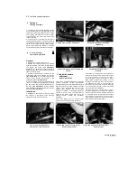
Fill a small heatproof container with
coolant mixture and place it on a stove. Using
an ohmmeter, connect the positive (+ve)
probe of the meter to the terminal on the
sender, and the negative (-ve) probe to the tip
of the sender. Using some wire or other
support suspend the sender in the coolant so
that
it
is
submerged.
Also
place
a
thermometer capable of reading temperatures
up to 120°C in the coolant so that its bulb is
close to the sender
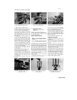
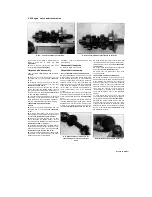
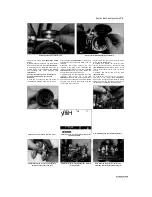
(see illustration). Note:
None of the components should be allowed to
directly touch the container.
Scaned by Stalker
A
A
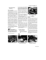
4.12 Fan switch testing set-up
I
A
5.10 Temperature sender testing set-up -
1991 to 1995 TDM models and all XTZ
models

