D.iHSin.nFPICUHi-DJSin
7*10 Brakes, wheels and tyres
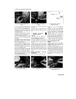
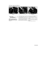
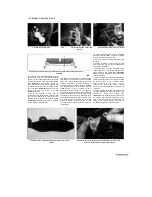
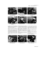
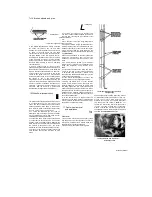
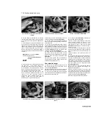
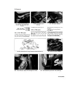
5.13a ... then depress the piston and
remove the circlip using a pair of internal
circlip pliers
13
Using circlip pliers, remove the circlip and
slide out the washer and pushrod (TDM models),
the piston assembly and the spring, noting how
they fit
(see illustration).
Lay the parts out in the
proper order to prevent confusion during
reassembly
(see illustration).
14
On TRX models, remove the fluid reservoir
hose union rubber cap, then remove the circlip
and detach the union from the master cylinder.
Discard the O-ring as a new one must be used.
Inspect the reservoir hose for cracks or splits and
renew if necessary.
15
Clean all parts with clean brake fluid. If
compressed air is available, use it to dry the parts
thoroughly
(make
sure
it's
filtered
and
unlubricated).
Caution: Do not, under any circumstances,
use a petroleum-based solvent to clean brake
parts.
16 Check the master cylinder bore for corrosion,
scratches, nicks and score marks. If damage or
wear is evident, the master cylinder must be
renewed. If the master cylinder is in poor
condition, then the calipers should be checked as
well. Check that the fluid inlet and outlet ports in
the master cylinder are clear.
17
The dust boot, circlip, piston, seal, primary
cup and spring are only available as a kit. Use all
of the new parts, regardless of the apparent
condition of the old ones. If the seal and cup are
not already on the piston, fit them according to
the layout of the old piston assembly.
18 Install the spring in the master cylinder. On
TDM models the spring's tapered end faces in,
and on TRX and XTZ models its tapered end
faces out.
19 Lubricate the piston, seal and cup with clean
brake fluid. Install the assembly into the master
cylinder, making sure it is the correct way round
(see illustration 5.13b).
Make sure the lips on
the cup do not turn inside out when they are
slipped into the bore. On TDM models slide in the
pushrod with its washer. Depress the piston and
install the new circlip, making sure that it locates
in the master cylinder groove
(see illustration
5.13a).
20
Install the rubber dust boot, making sure
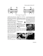
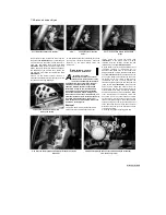
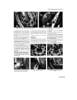
5.13b Lay out the internal parts as shown,
even if new parts are being used, to avoid
confusion on reassembly
the lip is seated correctly in the groove
(see
illustration 5.12).
21
On TRX models, fit a new O-ring onto the
reservoir hose union, then press the union into
the master cylinder and secure it with the circlip.
Fit the rubber cap over the circlip.
22 Inspect the reservoir cover rubber diaphragm
and renew it if it is damaged or deteriorated.
Installation
23 If removed, on TDM and TRX models, install
the brake light switch (see Chapter 9).
24 Attach the master cylinder to the handlebar
and, where marked, fit the clamp with its UP
mark facing up, aligning the top mating surfaces
of the clamp with the punch mark on the
handlebar
(see illustration).
Tighten first the
upper bolt, then the lower bolt to the torque
setting specified at the beginning of the Chapter
(see illustrations 5.8a and b).
25
Connect the brake hose(s) to the master
cylinder, using new sealing washers on each side
of the union(s), and aligning the hose(s) as noted
on removal
(see illustrations 5.6a and b).
Tighten the banjo bolt to the torque setting
specified at the beginning of this Chapter.
26 Install the brake lever (see Chapter 6), and
on TDM and XTZ models the rear view mirror.
27 On TRX models, mount the reservoir onto its
bracket and tighten the bolt securely
(see
illustration 5.7a).
Connect the reservoir hose to
the union and secure it with the clamp
(see
illustration 5.7b).
28
On TDM and TRX models, connect the
brake light switch wiring
(see illustrations 5.4a
and b).
On XTZ models, fit the switch into the
lever bracket.
29 Fill the fluid reservoir with new DOT 4 brake
fluid as described in
Daily (pre-ride) checks.
Refer to Section 8 of this Chapter and bleed the
air from the system.
30 Fit the rubber diaphragm, making sure it is
correctly seated, the diaphragm plate and the
cover or cap onto the master cylinder reservoir
(see illustration 5.3a).
On TRX models, fit the
cap clamp
(see illustration 5.3b).
31
Check the operation of the front brake before
riding the motorcycle.
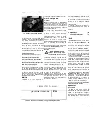
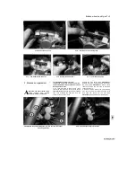
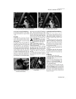
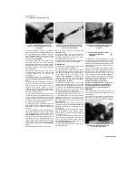
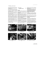
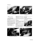
5.24 Align the clamp mating surfaces with
the punch mark on the handlebar
(arrowed)
6 Rear brake master cylinder - ^
removal, overhaul and
S
installation
J^
1
If the master cylinder is leaking fluid, or if the
lever does not produce a firm feel when the brake
is applied, and bleeding the brakes does not help
(see Section 8), and the hydraulic hoses are all in
good condition, then master cylinder overhaul is
recommended.
2 Before disassembling the master cylinder,
read through the entire procedure and make sure
that you obtain a new piston/seal kit. Also, you
will need some new DOT 4 brake fluid, some
clean rags and internal circlip
pliers. Note:
To
prevent damage to the paint from spilled brake
fluid, always cover the surrounding components
when working on the master cylinder.
Caution: Disassembly, overhaul and
reassembly of the brake master cylinder must
be done in a spotlessly clean work area to
avoid contamination and possible failure of
the brake hydraulic system components.
Removal
3 On TDM models, remove the seat, and on
XTZ models remove the right-hand side cover
(see Chapter 8).
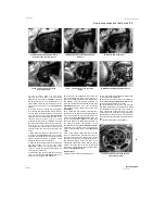
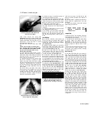
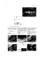
4 Unscrew the bolt securing the master cylinder
fluid reservoir to the frame, then remove the
reservoir cap and pour the fluid into a container
(see illustrations).
Release
Staned by Stalker
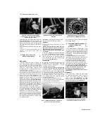
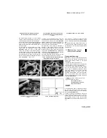
6.4a Master cylinder reservoir screw
(arrowed) - TDM models

