6*20 Frame, suspension and final drive
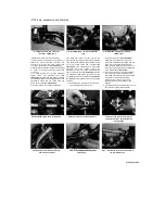
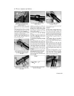
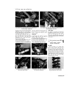
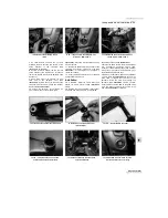
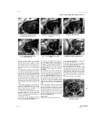
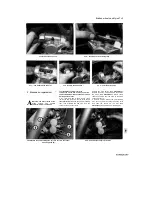
10.7a Linkage rod to linkage arm bolt (A), shock absorber lower
mounting bolt (B) - TRX models
10.7b Linkage rod to linkage arm bolt (A), shock absorber lower
mounting bolt (B) - XTZ models
securing the linkage rods to the linkage arm
(see
illustrations).
Unscrew the nut and withdraw the
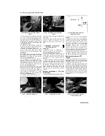
bolt securing the bottom of the shock absorber to
the suspension linkage arm. Swing the linkage
rods rearwards and the linkage arm down.
8 On TRX models, slacken the clamp screw
securing the reservoir to its holder and free the
hose from its clip on the frame
(see
illustrations).
Slip the reservoir out and feed it
through to the shock absorber.
9 Unscrew the nut on the shock absorber upper
mounting bolt
(see illustrations).
10
Support the shock absorber and withdraw
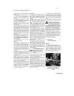
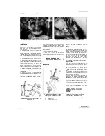
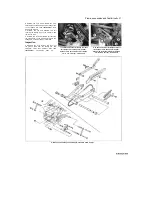
10.8a Slacken the clamp screw (arrowed) and
free the reservoir...
the upper mounting bolt, then manoeuvre the
shock down and out of the bottom of the
machine, on TRX models feeding the reservoir
through as you do.
Inspection
11
Inspect the shock absorber for obvious
physical damage and the coil spring for
looseness, cracks or signs of fatigue.
12
Inspect the damper rod for signs of bending,
pitting and oil leakage
(see illustration).
13
Inspect the pivot hardware at the top and
bottom of the shock for wear or damage.
.. and release the hose from its clip
(arrowed)
Installation
14
Installation is the reverse of removal. Apply
molybdenum disulphide grease to the shock
absorber and linkage rod pivot points. Install the
bolts and nuts finger-tight only until all
components are in position, then tighten the nuts
to the torque settings specified at the beginning
of the Chapter.
11 Rear suspension linkage
(TRX
§»
and XTZ models) - removal,
inspection and installation
Removal
1 Place the machine on an auxiliary stand.
Position a support under the rear wheel so that it
does not drop when the shock absorber lower
mounting bolt is removed, but also making sure
that the weight of the machine is off the rear
suspension so that the shock is not compressed.
2 Remove the seat (see Chapter 8). If required
for improved clearance, also remove the exhaust
system (see Chapter 4). On XTZ models, where
fitted, remove the rubber boot from around the
shock absorber lower mounting.
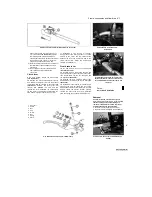
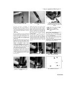
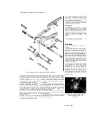
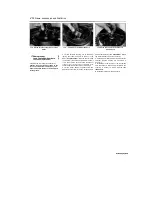
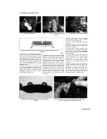
10.9a Shock absorber upper mounting
bolt (arrowed) - TRX models
10.9b Shock absorber upper mounting
bolt (arrowed) - XTZ models
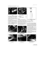
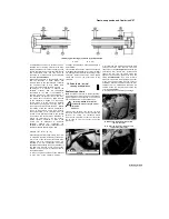
10.12 Look for cracks, pitting and oil
leakage on the damper rod (arrowed)
Scaned by Stalker
10.8b
1

