UNREGISTERED VERSION OF PICTURED
UNREGISTERED VI
Engine, clutch and transmission 2*49
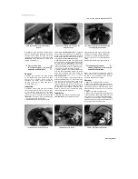
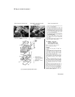
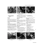
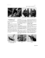
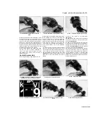
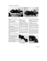
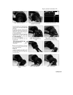
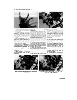
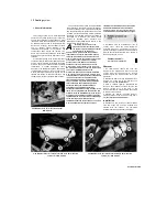
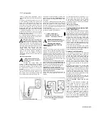
28.2 Measure the connecting rod side clearance using a feeler
gauge
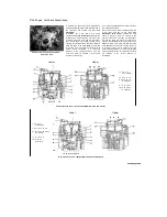
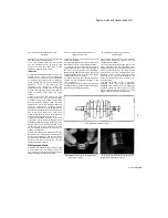
28.4 Unscrew the nuts (arrowed) and remove the connecting rods
28 Connecting rods
- removal,
inspection and installation
Note:
To remove the connecting rods
the engine must be removed from the frame and
the crankcases separated.
Removal
1 Remove the engine from the frame (see
Section 5) and separate the crankcase halves
(see Section 25).
2 Before removing the rods from the crankshaft,
measure the side clearance on each rod with a
feeler gauge
(see illustration).
If the clearance
between any rod is greater than the service limit
listed in this Chapter's Specifications, replace that
rod with a new one.
3 Using paint or a felt marker pen, mark the
relevant cylinder identity on each connecting rod
and cap. Mark across the cap-to-connecting rod
join and note the Y mark on each connecting rod
which must face to the left-hand side of the
engine to ensure that the cap and rod are fitted
the correct way around on reassembly. Note that
the number etched
across the rod and cap indicates rod size grade,
not cylinder number.
4 Unscrew the big-end cap nuts and separate
the cap from the crankpin
(see illustration).
Do not remove the bolts from the connecting
rods. Immediately install the relevant bearing
shells (if removed), bearing cap, and nuts on
each piston/connecting rod assembly so that
they are all kept together as a matched set to
ensure correct installation.
Inspection
5 Check the connecting rods for cracks and
other obvious damage.
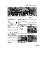
6 Apply clean engine oil to the piston pin, insert
it into the connecting rod small-end and check for
any freeplay between the two
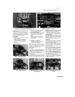
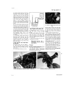
(see illustration).
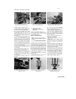
Measure the pin external and compare the result
to the specifications at the beginning of the
Chapter
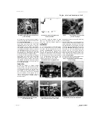
(see illustration).
If the piston pin is
worn below the service limit it should be
renewed.
7 Refer to Section 27 and examine the
connecting rod bearing shells. If they are scored,
badly scuffed or appear to have seized, new
shells must be installed. Always renew the shells
in the connecting rods as a set. If they are badly
damaged, check the corresponding crankpin.
Evidence of extreme
heat, such as discoloration, indicates that
lubrication failure has occurred. Be sure to
thoroughly check the oil pump and pressure relief
valve as well as all oil holes and passages before
reassembling the engine.
8 Have the rods checked for twist and bend
by a Yamaha dealer or engineer if you are in
doubt about their straightness.
Oil clearance check
9
Whether new bearing shells are being fitted
or the original ones are being re-used, the
connecting rod bearing oil clearance should
be checked prior to reassembly.
10 Clean the backs of the bearing shells and
the bearing locations in both the connecting rod
and cap.
11 Press the bearing shells into their locations,
ensuring that the tab on each shell engages the
notch
in
the
connecting
rod/cap
(see
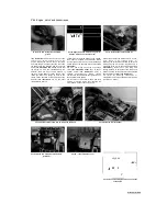
illustration).
Make sure the bearings are fitted in
the correct locations and take care not to touch
any shell's bearing surface with your fingers.
12
Cut a length of the appropriate size
Plastigauge (it should be slightly shorter than the
width of the crankpin). Place a strand of
Plastigauge on the (cleaned) crankpin journal.
13 Apply molybdenum disulphide grease to
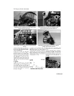
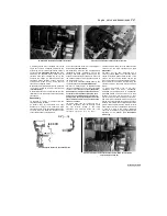
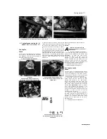
28.6a Slip the piston pin into the rod's
small-end and rock it back and forth to
check for looseness
28.6b Measure the external diameter of
the pin
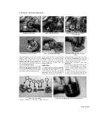
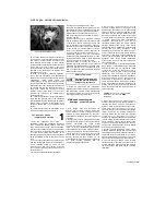
28.11 Make sure the tab (A) locates in the
notch (B)
Staned by Stalker

