


Appendix A: Planning Your Wireless Link
84
Version 1.0 Rev B - 08/00
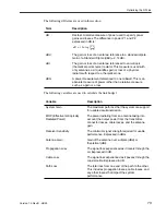
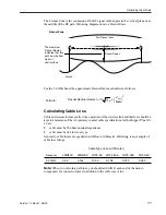
Minimal Clearance Above Obstructions
For the Hopper Plus 120-24, the absolute minimum clearance above obstructions
requirements are as follows (in meters):
¥
@ 2.4 GHz
Following are some example clearance requirements:
Note:
There is also a correction factor added to compensate for curvature of the earth.
This correction factor is not required when the correction value is negligible < 10 km.
Wi-LAN s Link Analysis Spreadsheet takes this variable into account automatically.
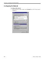
Installing Antennas
If your antennas will be located on a support structure, or on top of a tower, you should
have the antenna installed professionally.
Ensure the following:
¥
dipole antennas are oriented vertically (point up).
¥
antennas for the system have the same polarity (vertical, horizontal, or circular).
¥
connectors attaching the coaxial cable to the antenna are properly weatherproofed.
¥
a drip loop is formed at the building entrance, to prevent water flowing down the
coaxial cable and entering the installation building.
¥
the coaxial cable is secured to the supporting structure at one meter intervals. This
prevents wind damage and frost loading problems.
¥
the antenna is firmly attached to the mast to prevent it from falling, yet has some
flexibility so you can move the antenna to fine-tune its position.
¥
the coaxial cable is connected to the antenna and to the antenna port on both sides of
the link (base and remote stations).
¥
the antennas are grounded properly.
Metric
Distance
(km)
2.4 GHz
Clearance
(m)
Imperial
Distance
(miles)
2.4 GHz
Clearance
(ft)
0.5
2.4
0.5
10.0
1
3.4
1
14.3
2
4.9
2
20.5
3
6.0
3
25.7
5
8.0
5
34.9
8
10.6
8
48.3
10
12.3
10
57.6
15
16.6
15
83.8
3.4
m
d
km
×


