


Appendix A: Planning Your Wireless Link
76
Version 1.0 Rev B - 08/00
Optimizing Antenna Gain
To ensure the best range and interference suppression, the external antenna should be
directional, focusing the radio energy in one direction (toward the other end of the link). A
directional antenna focuses the RF energy to the intended station rather than
omni-directionally. This reduces interference from other systems operating at the same
frequency.
Note:
In some situations, you may want to use an omni-directional antenna in your
system design. For example, you would use an omni-directional antenna for a base station
with remote sites situated in a 360… path around it.
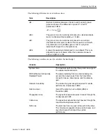
When you select an antenna, pay particular attention to the gain specification. When you
select an antenna for a remote station, select an antenna with a gain that provides at least
15 dB fade margin.
Antenna gain is specified in either dBi or dBd. When an antenna is specified in dBd, add
2.14 dB to the value to convert it to dBi.
Calculating Propagation Loss
The propagation loss is the attenuation (reduction) in RF signal energy as it travels
through space. In most wireless systems, losses through space are the major contributor to
signal attenuation. When you know the intended installation locations of the base and
remote stations, determine the physical line of sight distance and then calculate the RF
attenuation as follows:
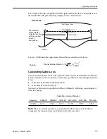
Working with the Fresnel Zone
It is essential that you locate your antennas at maximum above-ground height to ensure
that
1.
all ground-based obstructions are cleared from the Line of Sight path
2.
the Fresnel Zone is clear of obstructions
Formula:
Attenuation (dB) for 2.4 GHz band = 100 dB + 20log(d
km
)
where:
d
km
= Distance in Kilometers
100 dB = Pathloss Constant in the 2.4 GHz band


