


Optimizing the RF Link
Version 1.0 Rev B - 08/00
77
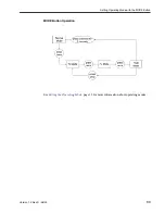
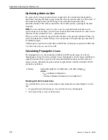
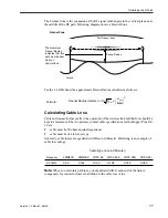
The Fresnel Zone is the expansion of the RF signal radio angles in the vertical plane near
the middle of the RF path. Following diagram shows a Fresnel Zone:
For the 2.4 GHz band, the approximate Fresnel Radius calculated as follows:
Calculating Cable Loss
Cable and connector losses affect the operation of the wireless link and therfore should be
kept to a minimum. The two primary coaxial cable specifications for the Hopper Plus 120-
24 are:
¥
cable must be 50 ohms nominal impedance
¥
cable must be of a low loss type
Generally, cable losses are specified in dB/foot or dB/meter. Following is an example of
cable loss ratings:
Note:
When you calculate path loss, you should add 1dB at each end of the link to
compensate for connector losses in addition to the cable loss value.
Formula:
Fresnel Radius (meters) =
Cable Type (loss in dB/meter)
Frequency
LMR400
LMR600
LDF2-50
LDF4-50ALDF5-50A LDF6-50
2.4 GHz
0.22
0.144
0.190
0.128
0.073
0.053
First Fresnel Zone
Line of Sight
Fresnel Radius
Ground
The maximum
Fresnel Radius
indicates that this
path must be kept
clear of
obstructions.
Fresnel Zone
3.4
d
km
d
km
8.12
----------
2
+


