
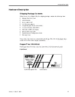


Hardware Description
Version 1.0 Rev B - 08/00
5
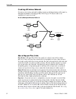
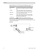
Items located on the back panel are described below:
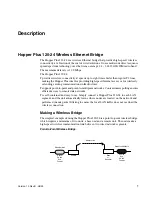
ANTENNA Connector
The antenna connector is located at the top left of the rear
panel. It is TNC (Threaded N-type Connector) male or
female. This port should always be connected to an
antenna directly or through a 50 ohm coaxial cable.
POWER Connector
3-pin power connector. See
Power Connector Pinout
, page
112 for detailed pinout illustration.
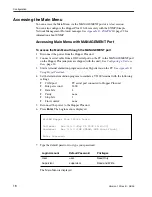
MODE Button
The mode button can be used to set the operating mode of
a unit without a terminal. See
Setting Operating Mode with
the MODE Button
, page 68 for information about the mode
button.
10/100 BASET
A standard RJ45 female connector. To connect to a PC
Ethernet card, you must use the crossover twisted-pair
cable (provided). To connect to a hub, use a straight-
through twisted-pair cable.
LINK LED
The color of the LED indicates the data rate and status of
the twisted-pair connection.
Green = 10 BaseT link, functioning properly.
Orange = 100 BaseT link, functioning properly.
Off = No link.


