
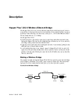


Description
4
Version 1.0 Rev B - 08/00
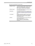
The the front panel connector and LEDs are described below. The color of a LED
indicates its status See
Front Panel LEDs
, page 111
for detailed information.
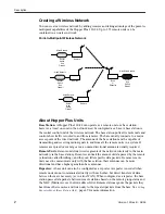
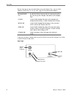
Connectors for power, antenna and wired network are located on the back panel, as well as
a mode button and a link LED.
Rear Panel
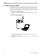
MANAGEMENT
Port
An RS-232, DB9 connector used to communicate with a
PC. Use this port to configure, test and set up the Hopper
Plus.
AIR LED
Color of LED indicates the status of the wireless link
during transmit, receive, or listen. Normal color: Orange.
MODE LED
Color of LED indicates the test status of the unit when
unit is in test mode. Normal color: Off.
WIRE LED
Color of LED indicates the status of the wire link during
transmit, receive, transmit and receive, or listen. Normal
color: Green, Red, Orange or Off.
POWER LED
Shows the status of the unit’s power. Normal color:
Green.
MODE button
LINK LED
Network
Port
Power Connector
Antenna
(TNC)
Connector


