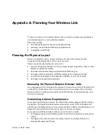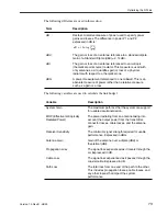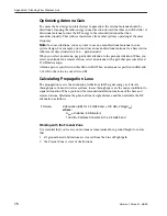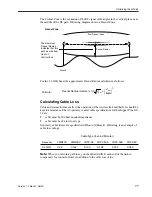
Link Budget Example
Version 1.0 Rev B - 08/00
79
Link Budget Example
The values for cable
and connector
losses in this
example are
only
for
illustration. You will
need to work these
out for your specific
installations.
Putting everything together, you must satisfy the following equations to have a successful
link:
Formulas:
System Gain + Antenna Gain
≥
Propagation Loss + Desired Fade
Cable Connector Losses
or
Actual Fade Margin
≥
System Gain + Antenna Gain - Propagation
Loss - Cable Losses - Connector Losses
and
Actual Fade Margin
≥
Desired Fade Margin
where:
System Gain = Tx Power - Rx Sensitivity
Antenna Gains = Tx Antenna Gain + Rx Antenna Gain
Cable Losses = Base Cable Remote Cable Losses
Connector Losses = Base System Connector Remote
System Connector Losses
Variables:
Desired Fade Margin
=
15 dB
Tx Power
=
18.5 dBm
Rx Sensitivity
=
-83 dBm
Tx Antenna Gain
=
11 dBi
Rx Antenna Gain
=
9 dBi
Propagation Loss for
desired range of 1km
=
100 + 20 x log(1) = 100 dB
Tx Cable Losses
(2m LMR400)
=
2 * 0.22 = 0.44 dB
Rx Cable Losses
(2m LMR 400)
=
2 * 0.22 = 0.44 dB
Tx Connector Losses
=
1 dB
Rx Connector Losses
=
1 dB
Variable
Calculations:
System Gain = 21 - (-79) = 100 dB
Antenna Gains = 11 + 9 = 20 dBi
Cable Losses = 0.44 + 0.44 = 0.88 dB
Connector Losses = 1 + 1 = 2 dB
Actual Fade
Margin
Calculation:
Actual Fade Margin = 100 + 20 - 100 - .88 - 2 = 17.12 dB
Analysis:
We have achieved the goal of Actual Fade Margin
≥
15 dB.


