


Appendix A: Planning Your Wireless Link
72
Version 1.0 Rev B - 08/00
¥
potential wind load and ice loading impact on the antenna
¥
regulatory restrictions, such as height, on antenna mast usage in the identified location
¥
grounding requirements. You must ensure that your antenna is properly grounded for
lightning and installed according to the relevant electrical code for the location.
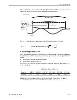
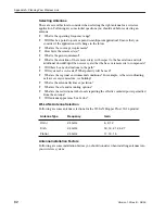
Determining Cable Requirements
If you are installing the antenna in an outdoor location, you will require 50 ohm coaxial
cable to connect the unit to the antenna. You should minimize the length of the coaxial
cable because the longer the cable is, the greater the cable losses are. You need to know
the required cable lengths before you install the unit.
Note:
You should use surge suppressors at the point of cable entry into the building.
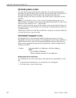
Calculating Fade Margins
You can calculate the fade margin of your wireless link after you ve identified the antenna
requirements. The fade margin enables you to predict the reliability of your wireless link.
See
Calculating Path Loss
on page 78 for more information about fade margins.
Determining Environmental Requirements
Hopper Plus 120-24 units must be located in a weatherproof environment with an ambient
temperature between 0… and 40… Celsius, and humidity from 0 to 95% non-condensing.
Consider the building, heating, and air conditioning required to ensure that the unit
operates within these conditions.
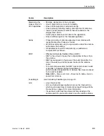
Optimizing the RF Link
Overview
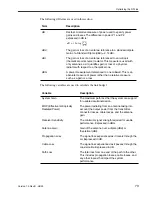
This section explains how to obtain optimal performance from your RF link. Proper path
planning ensures that each end of the RF link receives sufficient signal power to maintain
a desired Bit Error Rate (BER). The effectiveness and reliability of your RF link depends
on the following:
¥
antenna gain, beamwidth, F/B ratio, and cross-polarization discrimination
¥
distance between antennas and obstructions in the RF path
¥
above-ground height of the antennas
¥
length and type of coaxial cable connecting the Hopper Plus 120-24 and the antenna
The above factors will be used to calculate your link budget. The calculation indicates if
your radio link is feasible over a given distance and path and if your RF link meets
regulatory requirements. Link budgets are typically expressed in decibels (dB).


