


Appendix A: Planning Your Wireless Link
78
Version 1.0 Rev B - 08/00
Calculating Path Loss
Path loss describes the total RF attenuation throughout the system from Tx antenna to Rx
antenna. This includes the losses as the RF signal travels through space plus Tx and Rx
cable loss, and Tx and Rx connector loss. Use the following formula to calculate path loss:
Once you know the path loss, you can compare the value to the system gain value. If the
system gain value is greater than the path loss, the link is feasible. See
Working with
System Gain
on page 74 for more information about system gain.
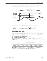
Working with the Fade Margin
Total antenna gain
is:
Tx Antenna Gain +
Rx Antenna Gain
The amount by which the system gain plus the total antenna gain exceeds the path loss is
called the fade margin. As calculated, the fade margin is the number of dB that the
received signal strength exceeds the minimum receiver sensitivity. You require some level
of fade margin for any wireless system. The fade margin compensates for RF path fading
due to weather conditions or objects that induce multipath interference.
The Wi-LAN recommended fade margin for the Hopper Plus 120-24 is a minimum of
15 dB. The sum of the cable losses, connector losses, propagation losses, and the 15 dB
required fade margin should be less than the sum of the system gain and antenna gain.
Formula:
Path Loss = Tx and Rx Cable Loss + Tx and Rx Connector Loss +
Propagation Loss


