


Version 1.0 Rev B - 08/00
71
Appendix A: Planning Your Wireless Link
To ensure an effective and reliable wireless link, you need to perform some preliminary
network planning
before
you install any hardware.
These steps include:
¥
determining the physical layout of your planned link
¥
planning your antenna and fade margin requirements
¥
configuring your RF link.
Planning the Physical Layout
Before you install the units, you must determine the physical locations for each
component of the Hopper Plus 120-24 wireless system.
When you plan the physical layout, you need to:
¥
measure the physical distance between each pair of units using GPS, a map, or other
distance measurement method
¥
determine antenna mast height requirements and fade margins
¥
determine cable requirements, including routing, between antenna and unit
¥
calculate the fade margin to determine the reliability of your wireless link
¥
determine environmental requirements
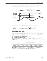
Measuring the Physical Distance Between Units
Use a mapping method to determine the distance between sites, and check the radio path
to identify any obstructions in the site path between the two antennas. Due to the high
frequency and low output power permitted in the ISM bands, no obstructions may exist
between two antennas.
Determining Antenna Requirements
If you plan to install the unit indoors, the rubber duck antenna shipped with the unit may
be adequate. The signal from this antenna can penetrate several walls, although metal
obstructions or building features such as elevator shafts can deflect or inhibit radio waves.
Empirical testing is advised in this case because all interiors are unique.
If you plan to install the antennas outdoors you will need to consider
¥
obtaining permission from building owners if you intend to install your antenna on a
rooftop
¥
the height of the antenna required to ensure a radio Line of Sight between two
antennas that define the RF link


