


Testing Basic Operation
Version 1.0 Rev B - 08/00
13
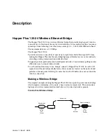
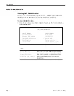
Performing a Simple Network Test
To perform a simple network test
1.
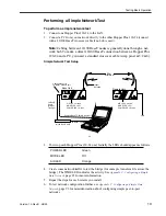
Connect one Hopper Plus 120-24 to the LAN.
2.
Connect a PC from your network directly to the other Hopper Plus 120-24 (connect
with a 10/100 BaseT crossover cable if no hub is used).
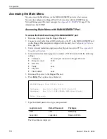
Note:
Cabling between 10/100 BaseT nodes is generally done through a net-
work hub. To make a direct 10/100 BaseT connection between a Hopper Plus
120-24 and a PC, you need a standard crossover cable (swap pins 1&3; 2&6).
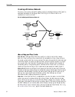
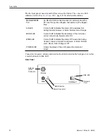
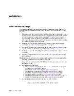
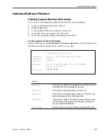
Simple Network Test Setup
3.
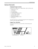
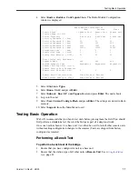
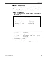
Power up each Hopper Plus 120-24 unit. Initially the LEDs should appear as follows:
4.
Create some network traffic to test the bridge (for example, transfer a file across the
bridge). The WIRE LED indicates the activity. See
Appendix C: Configuring a Simple
Data Network
, page 93
for more information.
5.
Repeat the steps for each remote you install.
6.
To test network configuration further, see
Appendix C: Configuring a Simple Data
Network
, page 93 for moreinformation about configuring simple peer-to-peer
networks.
POWER LED
Green
MODE LED
Off
AIR LED
Orange
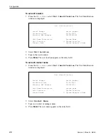
AIR LED = orange
Base Unit
Remote Unit
MODE LED = Off
POWER LED = Green
AIR LED = orange
MODE LED = Off
POWER LED = Green
PC
LAN
10/100 BaseT HUB
10 BaseT Cable
Direct 10 BaseT Cable (Crossover)
A
IR
M
O
D
E
W
IR
E
P
O
W
E
R
PL
US
A
IR
M
O
D
E
W
IR
E
P
O
W
E
R
PL
US
20m
minimum
Indoor
Antenna
Cables connect to
10 BaseT network port
(Straight
Through)
Cable
10 BaseT


