EUROBLOC
SERVICE MANUAL FOR HOIST
123/212
This document and the information contained herein, is the exclusive property of Verlinde S.A.S. and represents a non-public, confidential and proprietary trade secret that
may not be reproduced, disclosed to third parties, altered or otherwise employed in any manner whatsoever without the express written consent of Verlinde S.A.S.
Copyright © (2013) Verlinde S.A.S. All rights reserved.
06/2015
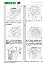
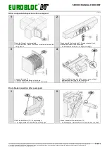
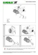
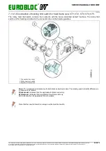
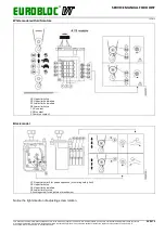
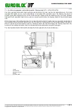
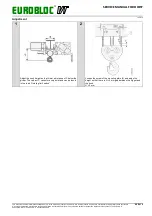
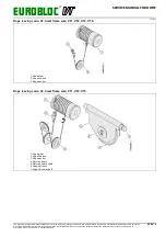
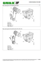
7.1.12.3 Construction of hoisting limit switch for hoist frame size: VT1, VT2, VT3, VT4, VT5.
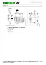
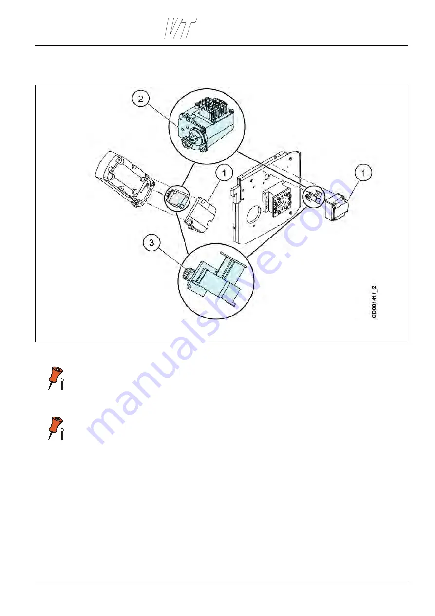
The rotary hoist limit switch contains four contacts, with the below described default functions. The rotary limit
switch unit for hoisting is located in the connection box on the hoisting gearbox.
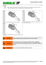
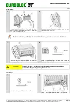
1. Connection box cover
2. White hoist limit switch
3. Black hoist limit switch
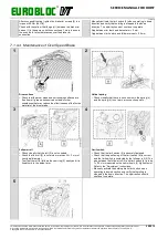
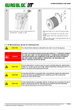
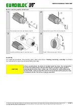
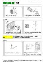
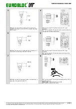
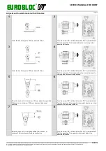
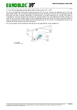
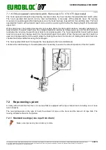
Note: The procedure is almost same for both black and white models. The marking used to identify difference in
procedure is as follows:
Black model: indicates that it is applicable for black model only
White model: indicates that is applicable for white model only
All: indicates that it is applicable for both models.
Note that the new limit switch is always a white hoist limit switch.


