EUROBLOC
SERVICE MANUAL FOR HOIST
71/212
This document and the information contained herein, is the exclusive property of Verlinde S.A.S. and represents a non-public, confidential and proprietary trade secret that
may not be reproduced, disclosed to third parties, altered or otherwise employed in any manner whatsoever without the express written consent of Verlinde S.A.S.
Copyright © (2013) Verlinde S.A.S. All rights reserved.
06/2015
3
4
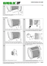
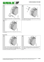
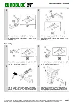
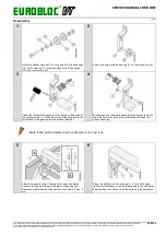
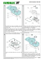
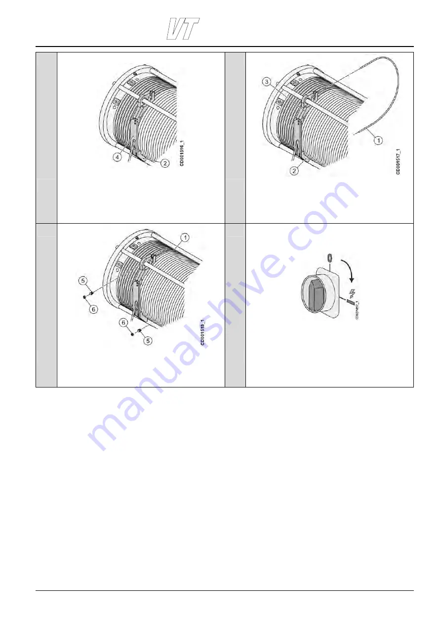
Pass the rope through the joint plate (4) and place the lower
half (2) of the guide frame against the drum groove next to the
groove from which the rope leaves the drum.
With the rope passing through both the joint plate (4) and the
lower half (2) of the guide frame, fix the joint plate and the
lower half together with four screws.
Pass the “U” shaped rod (1) around the rope drum and into
the groove that travels around the rope drum from the upper
half (3) to the lower half (2) of the guide frame. Pass the ends
of the rod through both frame halves.
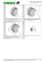
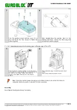
5
6
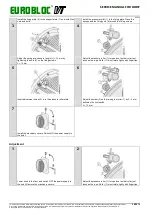
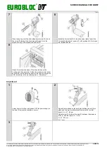
Pass the ends of the rod (1) through the sleeves (5) and press
the sleeves into the sockets in the frame halves.
Fix the rod in place with the two self-locking nuts (6). Follow
the adjustment instructions in order to get the nuts to the
proper tightness.
Install the machinery covers. Switch ON the power supply to
the hoist.

