EUROBLOC
SERVICE MANUAL FOR HOIST
134/212
This document and the information contained herein, is the exclusive property of Verlinde S.A.S. and represents a non-public, confidential and proprietary trade secret that
may not be reproduced, disclosed to third parties, altered or otherwise employed in any manner whatsoever without the express written consent of Verlinde S.A.S.
Copyright © (2013) Verlinde S.A.S. All rights reserved.
06/2015
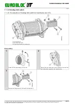
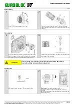
Reassembly
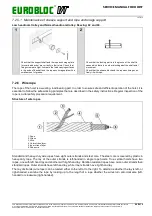
1
2
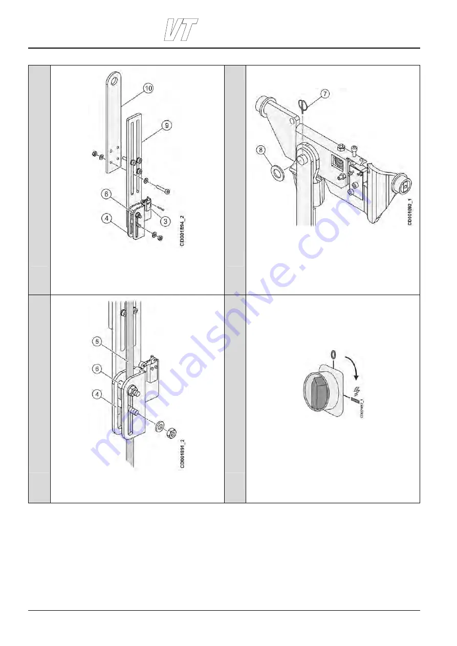
Place the bushings (6) on the screws. Install the trigger (4)
with nuts and washers. Hand tighten the nuts. Install the limit
switch (3) with screws. Fix the mounting plate (9) to the base
plate (10) with screws and washers. Tighten the screws and
test the mechanical action of the switch by raising up the
trigger (4).
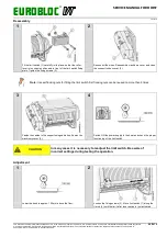
Hang limit switch assembly to the shaft and lock it in place
with locking ring (7) and washer (8). Make sure that the
locking ring is correctly assembled. Adjust the limit switch arm
to correct length.
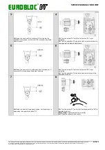
3
4
Loosen the nuts and remove the trigger (4). Pass the rope (5)
through the trigger (4) and reinstall it. Tighten the screws to
torque value 45 Nm. Make sure that trigger slides freely on the
limit switch support.
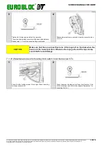
Install the machinery covers and switch ON the power to the
hoist.

