


Application functions
181
1.
Byte1 of the parameter [position control switch] is used to enable the infinite position mode function.
When it is set to 0x00, the infinite position control mode is disabled; when it is set to 0x01, the normal
infinite position control mode is enabled; when it is set to 0x02, the modulo infinite position control
mode is enabled.
2.
The encoder multi-turn upper limit value is valid when the [infinite position mode] is enabled, and is
only applicable to absolute encoders whose multi-turn resolution is not 0. Moreover, the set value of
this parameter must be within the range specified by the parameter [interface encoder multi-turn
bits] (0x2017).
How to use
8.4.3
The methods about setting and using the [normal infinite position
control mode] are as follows.
1.
Set Byte1 of the parameter [position control switch] to 0x01 to enable the normal infinite position control mode;
2.
Set the [Encoder Multi-Turn Upper Limit Value] to 0;
3.
Restart the servo drive to make the parameter changes take effect;
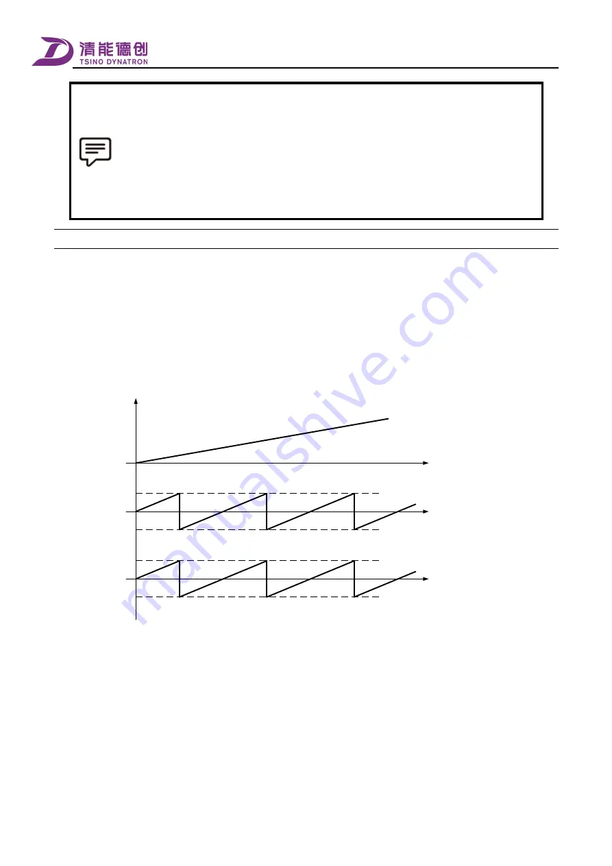
4.
When the target position value issued by the upper computer increases progressively to the upper limit, it shall be
switched to the lower limit value and then increased progressively, and the actual value of the drive position changes with
it, as shown in the figure below.
Position demand
upper limit
2^31-1 Inc
Position demand
lower limit
-2^31 Inc
Actual operating
position of the device
Target position value
of upper computer
Actual position
value of the driver
Position demand
upper limit
2^31-1 Inc
Position demand
lower limit
-2^31 Inc
5.
When the target position value issued by the upper computer decreases progressively to the lower limit, it shall be
switched to the upper limit value and then decreased progressively, and the actual value of the drive position changes with
it, as shown in the figure below.
Summary of Contents for CoolDrive Series
Page 29: ...Preface 17 T2 model ...
Page 30: ...Preface 18 T3 model ...
Page 31: ...Preface 19 T4 model ...
Page 230: ...Monitoring 218 ...